STM32程序的编译、链接和启动分析 |
您所在的位置:网站首页 › 启动代码主要完成哪些功能 › STM32程序的编译、链接和启动分析 |
STM32程序的编译、链接和启动分析
|
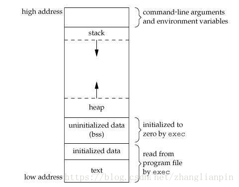
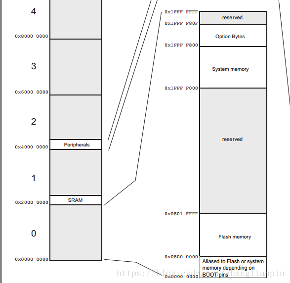
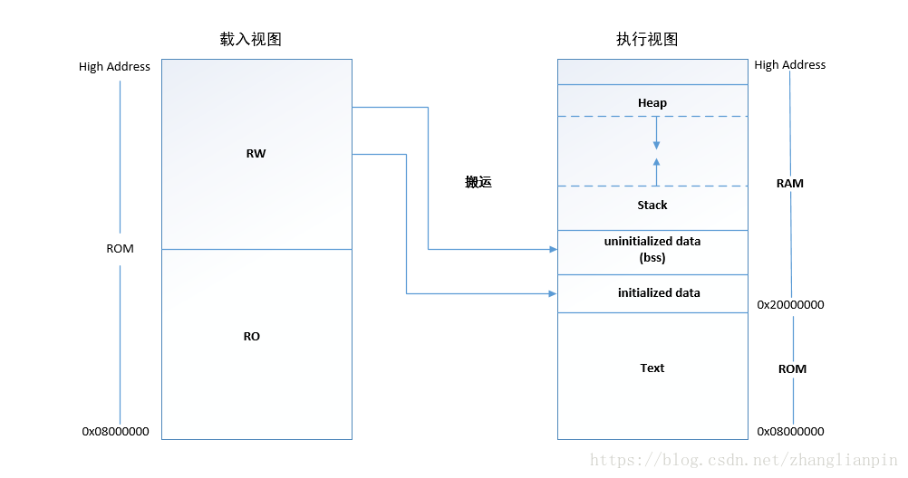
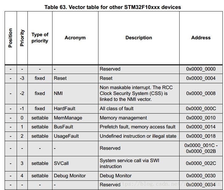
本篇文章以STM32为硬件平台,使用GNU GCC作为开发工具,详细分析Compile 、Link 、Loader的过程以及Image(二进制程序)启动的详细分析。整个过程分析涉及到RW可读写段从Flash到Mem的Copy,BSS段的初始化,Stack和Heap的初始化,C库函数移植、利用Semihosting 实现基本的IO等内容。基本可以让你从更深刻的层面理解Source -> Compile -> link -> run的整个过程。理解了这些个之后,你就对那些从语言编程层面来说难于理解的问题自然领会了,比如:为什么C语言规范里会提到变量的作用域和生命周期?全局变量和局部变量的区别到底在哪?等等一些看起来是规定的东西,工科科学里一切不自然的概念都需要你用心去理解,去实践,达到自然的状态才有可能去解决实际遇到的问题,规则只是思想包袱,不会产生任何价值,大部分情况下会阻碍你解决问题。 裸机程序的整体说明我们都熟悉有操作系统支持的应用程序开发,比如 Linux下C语言的开发。我们可以不用关心程序启动的细节,同时我们一般还可以使用各种方便的lib 库,比如基本的IO操作(printf scan),动态分配内存操作(malloc),文件操作(fopen fwrite fread)等。有操作系统支持的情况下,程序的编译、链接、启动都是有操作系统支持的,常用的编程库函数使用的是标准的C库。 那如果没有OS支持的情况下,想实现上面这些功能的话,该怎么做呐?这种情况就叫 Bare Metal (裸)程序开发。在嵌入式开发中是比较常见的情况,本blog 主要讲解基于Cortex-M3 的裸程序开发。本裸机程序实现了 基本IO,动态内存分配,基本函数库等功能。 主程序(main)验证了那些功能主程序验证了基本的Startup,基本的IO功能,malloc功能,打印了全局变量和局部变量的地址(用于理解全局变量和局部变量的区别)。 其主程序代码如下: #include #include #include "diag/Trace.h" int test = 10; int main(int argc, char* argv[]) { int local_test = 8; int i; float temp = 0.01; int *arr_malloc = NULL; arr_malloc = malloc(10*sizeof(int)); if(!arr_malloc) { trace_puts("malloc error!"); exit(1); } memcpy(arr_malloc,"123456789",9); arr_malloc[9]=NULL; trace_printf("Testing malloc \n"); trace_printf("the string =%s\n", arr_malloc); // Send a greeting to the trace device (skipped on Release). trace_puts("Hello ARM World by Linc Zhang!"); // At this stage the system clock should have already been configured // at high speed. trace_printf("System clock: %u Hz\n", SystemCoreClock); trace_printf("the [test]=0x%x\n",test); trace_printf("the [local_test]=0x%x\n",local_test); trace_printf("the address[test]=0x%x\n",&test); trace_printf("the address[local_test]=0x%x\n",&local_test); trace_printf("the float type value temp =0x%f\n",temp); timer_start(); blink_led_init(); uint32_t seconds = 0; // Infinite loop while (1) { } // Infinite loop, never return. } 如何实现的startup还是和有OS支持的情况下来对比,有OS的情况下分析一个Project,一般会从3个方面来进行分析:一是看源代码的组织形式;一是看Compile && Link过程(即Makefile);三是看Run时的情况(一般看运行起来后几个Process,几个Thread,以及他们之间的关系)。分析完这3个方面后,整个project从静到动,以及动静之间的转换都包括了,也就掌握了整个的Project。 在没有OS的情况下,1 2 两个方面是一样的,只不过程序运行的基础环境不一样,裸机程序运行需要考虑的细节多一些。裸机程序需要考虑的基本问题有: 编译生成的可执行程序结构是什么样的?整个可执行程序的入口在哪?需要将可执行程序下载到什么地方?程序运行前需要做哪些准备工作?C语言运行需要什么样的环境?我们按照上面说的方法,从3各方面出发,分析我们的Project。 源代码: 顶层目录: . ├── Debug ├── include ├── ldscripts ├── src └── system其中src目录是Application层的主逻辑代码,其中main.c就在src目录中,是业务逻辑层的主代码。 include目录是Application层的interface 说明文件。 system 目录是和启动有关系的代码。 ldscripts目录是link 脚本,主要告诉ld(链接器)如何链接各个Objects文件为可执行程序. Debug目录是个编译目录,里面包含各种Makefile。 更详细的项目目录结构: . ├── Debug │ ├── hello.elf │ ├── hello.hex │ ├── hello.map │ ├── makefile │ ├── objects.mk │ ├── sources.mk │ ├── src │ │ ├── BlinkLed.d │ │ ├── BlinkLed.o │ │ ├── main.d │ │ ├── main.o │ │ ├── subdir.mk │ │ ├── Timer.d │ │ ├── Timer.o │ │ ├── _write.d │ │ └── _write.o │ └── system │ └── src ├── include │ ├── BlinkLed.h │ ├── stm32f10x_conf.h │ └── Timer.h ├── ldscripts │ ├── libs.ld │ ├── mem.ld │ └── sections.ld ├── src │ ├── BlinkLed.c │ ├── main.c │ ├── Timer.c │ └── _write.c └── system ├── include │ ├── arm │ ├── cmsis │ ├── cortexm │ ├── diag │ └── stm32f1-stdperiph └── src ├── cmsis ├── cortexm ├── diag ├── newlib └── stm32f1-stdperiph这里简单说明下system 目录,cmsis主要是soc相关的初始化代码,cortexm是Cortex-M3的启动相关代码,diag是使用Semihosting实现了基本的IO,newlib是newlib移植需要实现的函数,stm32f1-stdperiph 是soc片上的外设资源的Driver。 编译&&链接: 当然是直接 make 喽。 编译的模板,自己根据实际文件名进行修改 arm-none-eabi-gcc -mcpu=cortex-m3 -mthumb -Og -fmessage-length=0 -fsigned-char -ffunction-sections -fdata-sections -ffreestanding -fno-move-loop-invariants -Wall -Wextra -g3 -DDEBUG -DUSE_FULL_ASSERT -DTRACE -DOS_USE_TRACE_SEMIHOSTING_DEBUG -DSTM32F10X_MD -DUSE_STDPERIPH_DRIVER -DHSE_VALUE=8000000 -I"../include" -I"../system/include" -I"../system/include/cmsis" -I"../system/include/stm32f1-stdperiph" -std=gnu11编译说明:编译单个文件其实还是挺简单,只是添加了一些功能性的宏定义。 链接的模板,自己需要添加Objects文件 arm-none-eabi-g++ -mcpu=cortex-m3 -mthumb -Og -fmessage-length=0 -fsigned-char -ffunction-sections -fdata-sections -ffreestanding -fno-move-loop-invariants -Wall -Wextra -v --verbose -g3 -T mem.ld -T libs.ld -T sections.ld -nostartfiles -Xlinker --gc-sections -L"../ldscripts" -u _printf_float -Wl,-Map,"hello.map" --specs=nano.specs -o "hello.elf"链接说明:链接时使用了-nostartfiles,含义是不使用Crt0.o 提供的启动代码,库函数还是使用arm-linux-gcc提供的new-lib。 映像结构&&运行: 有操作系统的情况下,我们不需要关心可执行映像的具体结构,一个可执行程序文件从静态文件到动态运行这个过程叫Loader&&Run。这个过程是由OS来完成的,应用程序级别的开发是不需要关心这些细节的。对OS如何处理Link&&Loader这些细节感兴趣的,可以参考书籍: 1. 程序员的自我修养 2. Linkers and Loaders 我们这里处理的是裸程序的启动细节问题,首先我们要知道的是通过编译器和链接器之后得到的二进制可执行映像的结构。也就是说得出的那个 *.bin 文件里面长啥样?一图胜万言,上张图先。 我们大家都知道冯.诺依曼架构的计算机,它的基本思想是把“做事情的步骤和所需要的资源都提前编写好,然后让计算机自己根据需要读取操作步骤和资源,实现部分的计算自动化”。计算机的设计思想可谓是精妙的,实现真正的计算自动化也是很多科学家和工程师的夙愿。上面所说的做事情的步骤在计算机领域叫指令,所需要的资源在计算机领域叫数据。从计算机体系结构角度去看可执行映像的话,其实也就分为指令和数据两个大的部分。指令部分还是比较单一的,把各个源文件中的指令部分最后都汇聚到一起,形成所谓的text段。从功能上分,代码段只是需要CPU去读取,不需要修改,因为可以将其放在RO存储器里。数据这个部分从功能上来看,它必须支持读写,也即数据段执行时必须位于RW存储器里。从功能细节上分数据段又分为BSS段,Data段,Stack段,Heap段。从计算机体系结构角度来一一分析,从数据的生存周期角度来看,有的数据的生存周期和程序的生存周期是一致的(全局变量),有的数据的生存周期是根据使用情况即时分配和释放的(局部变量、malloc动态分配的变量)。BSS段和Data段属于全生命周期的数据,在源程序里主要是那些在文件域定义的全局变量和使用static关键字定义的全生命周期变量,Data是那些在程序里定义变量时初始化为固定值的量,BSS段是那些在程序里定义变量时未初始化的变量,这些变量在映像真正执行前会自动初始化为0。对BSS段再多说一句,BSS段在映像文件里并不占用具体的空间,因为没有任何具体的信息,只需要在映像文件中提供BSS段的起始地址和大小信息即可。在映像文件实际执行前,把BSS段要求的Data区域在实际RAM中预留出来并把这些区域初始化为0。短生命周期的数据包括Heap和Stack,它们的特点是随用随申请,用完就释放,比较灵活。Heap是一段预留出来的大空间,可以根据需求随时申请和释放,就是我们常见的malloc free函数操作的空间就是Heap 空间,这部分空间在映像里是独立出来的一段空间,见上面的程序映像图。Stack也是独立预留出来的一段连续数据空间,它的作用还挺多,想更进一步了解的请看Stack在函数调用、中断(异常)、RTOS中的应用。 从程序映像角度来看,就是代码段和根据功能划分的一些数据段组成的,使用映像资源最关键的就是要知道每条指令或者具体的变量在映像文件中的Offset。也就是我们常说的Address,我们在裸机环境下所说的Address就是真实的物理地址(Physical Address)。 程序映像的事情说的差不多了,下面就得以STM32F103RBT6这种具体的Soc和arm-linux-gcc这种具体的compiler&&linker来进行详细说明。我们编译出来的映像的具体结构是什么样?整个可执行程序的入口在哪里?每个段的具体地址如何获取?可执行程序在执行前都做了哪些准备工作?下面我们来一一详细道来。 先来看看STM32F103RBT6这个soc的Memory map,还是来张图吧。 我们看到RO存储Flash Memory的地址段是:0x08000000–0x0801FFFF 共128K。 RW存储SRAM的地址段是:0x20000000–0x20004FFF 共20K。 我们Soc的启动配置是从0x08000000地址开始启动。为节约RAM空间,我们启动时映像的代码段不搬运,直接读取Flash Memory,数据段需要可读写,因此需要将所有的数据段搬移到RAM中去。大致情况见下图: 硬件情况就是这样,下面开始分析如何产生符合这款Soc的映像文件。下面一个重要的Tool出厂,link script,它控制着如何产生最终的映像文件。在分析具体的link script之前,先来说link script 里最重要的概念,Address && Offset,前面也说了,到了映像文件格式这一层面,也就剩下各种连续的内容(段)和地址(Address)了,因此地址对映像来说是一个十分重要的资源。link script 无非就是告诉链接器哪段东西放在哪个地址上。那些段需要搬运,当然搬运也是需要地址的。 来看看我们项目中用到的link script: 分连个层面来看,一是Memory Map相关的,一是段分配相关的。 先看Memory Map, /* * Memory Spaces Definitions. * * Need modifying for a specific board. * FLASH.ORIGIN: starting address of flash * FLASH.LENGTH: length of flash * RAM.ORIGIN: starting address of RAM bank 0 * RAM.LENGTH: length of RAM bank 0 * * The values below can be addressed in further linker scripts * using functions like 'ORIGIN(RAM)' or 'LENGTH(RAM)'. */ MEMORY { RAM (xrw) : ORIGIN = 0x20000000, LENGTH = 20K CCMRAM (xrw) : ORIGIN = 0x00000000, LENGTH = 0 FLASH (rx) : ORIGIN = 0x08000000, LENGTH = 128K FLASHB1 (rx) : ORIGIN = 0x00000000, LENGTH = 0 EXTMEMB0 (rx) : ORIGIN = 0x00000000, LENGTH = 0 EXTMEMB1 (rx) : ORIGIN = 0x00000000, LENGTH = 0 EXTMEMB2 (rx) : ORIGIN = 0x00000000, LENGTH = 0 EXTMEMB3 (rx) : ORIGIN = 0x00000000, LENGTH = 0 MEMORY_ARRAY (xrw) : ORIGIN = 0x00000000, LENGTH = 0 } /* * For external ram use something like: RAM (xrw) : ORIGIN = 0x68000000, LENGTH = 20K */定义了一个RO存储和一个RAM存储,地址空间和Soc硬件手册一致。 再来看看各种段设置的情况, /* * Default linker script for Cortex-M (it includes specifics for STM32F[34]xx). * * To make use of the multi-region initialisations, define * OS_INCLUDE_STARTUP_INIT_MULTIPLE_RAM_SECTIONS for the _startup.c file. */ /* * The '__stack' definition is required by crt0, do not remove it. */ __stack = ORIGIN(RAM) + LENGTH(RAM); _estack = __stack; /* STM specific definition */ /* * Default stack sizes. * These are used by the startup in order to allocate stacks * for the different modes. */ __Main_Stack_Size = 1024 ; PROVIDE ( _Main_Stack_Size = __Main_Stack_Size ) ; __Main_Stack_Limit = __stack - __Main_Stack_Size ; /* "PROVIDE" allows to easily override these values from an * object file or the command line. */ PROVIDE ( _Main_Stack_Limit = __Main_Stack_Limit ) ; /* * There will be a link error if there is not this amount of * RAM free at the end. */ _Minimum_Stack_Size = 256 ; /* * Default heap definitions. * The heap start immediately after the last statically allocated * .sbss/.noinit section, and extends up to the main stack limit. */ PROVIDE ( _Heap_Begin = _end_noinit ) ; PROVIDE ( _Heap_Limit = __stack - __Main_Stack_Size ) ; /* * The entry point is informative, for debuggers and simulators, * since the Cortex-M vector points to it anyway. */ ENTRY(_start) /* Sections Definitions */ SECTIONS { /* * For Cortex-M devices, the beginning of the startup code is stored in * the .isr_vector section, which goes to FLASH. */ .isr_vector : ALIGN(4) { FILL(0xFF) __vectors_start = ABSOLUTE(.) ; __vectors_start__ = ABSOLUTE(.) ; /* STM specific definition */ KEEP(*(.isr_vector)) /* Interrupt vectors */ KEEP(*(.cfmconfig)) /* Freescale configuration words */ /* * This section is here for convenience, to store the * startup code at the beginning of the flash area, hoping that * this will increase the readability of the listing. */ *(.after_vectors .after_vectors.*) /* Startup code and ISR */ } >FLASH .inits : ALIGN(4) { /* * Memory regions initialisation arrays. * * Thee are two kinds of arrays for each RAM region, one for * data and one for bss. Each is iterrated at startup and the * region initialisation is performed. * * The data array includes: * - from (LOADADDR()) * - region_begin (ADDR()) * - region_end (ADDR()+SIZEOF()) * * The bss array includes: * - region_begin (ADDR()) * - region_end (ADDR()+SIZEOF()) * * WARNING: It is mandatory that the regions are word aligned, * since the initialisation code works only on words. */ __data_regions_array_start = .; LONG(LOADADDR(.data)); LONG(ADDR(.data)); LONG(ADDR(.data)+SIZEOF(.data)); LONG(LOADADDR(.data_CCMRAM)); LONG(ADDR(.data_CCMRAM)); LONG(ADDR(.data_CCMRAM)+SIZEOF(.data_CCMRAM)); __data_regions_array_end = .; __bss_regions_array_start = .; LONG(ADDR(.bss)); LONG(ADDR(.bss)+SIZEOF(.bss)); LONG(ADDR(.bss_CCMRAM)); LONG(ADDR(.bss_CCMRAM)+SIZEOF(.bss_CCMRAM)); __bss_regions_array_end = .; /* End of memory regions initialisation arrays. */ /* * These are the old initialisation sections, intended to contain * naked code, with the prologue/epilogue added by crti.o/crtn.o * when linking with startup files. The standalone startup code * currently does not run these, better use the init arrays below. */ KEEP(*(.init)) KEEP(*(.fini)) . = ALIGN(4); /* * The preinit code, i.e. an array of pointers to initialisation * functions to be performed before constructors. */ PROVIDE_HIDDEN (__preinit_array_start = .); /* * Used to run the SystemInit() before anything else. */ KEEP(*(.preinit_array_sysinit .preinit_array_sysinit.*)) /* * Used for other platform inits. */ KEEP(*(.preinit_array_platform .preinit_array_platform.*)) /* * The application inits. If you need to enforce some order in * execution, create new sections, as before. */ KEEP(*(.preinit_array .preinit_array.*)) PROVIDE_HIDDEN (__preinit_array_end = .); . = ALIGN(4); /* * The init code, i.e. an array of pointers to static constructors. */ PROVIDE_HIDDEN (__init_array_start = .); KEEP(*(SORT(.init_array.*))) KEEP(*(.init_array)) PROVIDE_HIDDEN (__init_array_end = .); . = ALIGN(4); /* * The fini code, i.e. an array of pointers to static destructors. */ PROVIDE_HIDDEN (__fini_array_start = .); KEEP(*(SORT(.fini_array.*))) KEEP(*(.fini_array)) PROVIDE_HIDDEN (__fini_array_end = .); } >FLASH /* * For some STRx devices, the beginning of the startup code * is stored in the .flashtext section, which goes to FLASH. */ .flashtext : ALIGN(4) { *(.flashtext .flashtext.*) /* Startup code */ } >FLASH /* * The program code is stored in the .text section, * which goes to FLASH. */ .text : ALIGN(4) { *(.text .text.*) /* all remaining code */ /* read-only data (constants) */ *(.rodata .rodata.* .constdata .constdata.*) *(vtable) /* C++ virtual tables */ KEEP(*(.eh_frame*)) /* * Stub sections generated by the linker, to glue together * ARM and Thumb code. .glue_7 is used for ARM code calling * Thumb code, and .glue_7t is used for Thumb code calling * ARM code. Apparently always generated by the linker, for some * architectures, so better leave them here. */ *(.glue_7) *(.glue_7t) } >FLASH /* ARM magic sections */ .ARM.extab : ALIGN(4) { *(.ARM.extab* .gnu.linkonce.armextab.*) } > FLASH . = ALIGN(4); __exidx_start = .; .ARM.exidx : ALIGN(4) { *(.ARM.exidx* .gnu.linkonce.armexidx.*) } > FLASH __exidx_end = .; . = ALIGN(4); _etext = .; __etext = .; /* MEMORY_ARRAY */ /* .ROarraySection : { *(.ROarraySection .ROarraySection.*) } >MEMORY_ARRAY */ /* * The secondary initialised data section. */ .data_CCMRAM : ALIGN(4) { FILL(0xFF) *(.data.CCMRAM .data.CCMRAM.*) . = ALIGN(4) ; } > CCMRAM AT>FLASH /* * This address is used by the startup code to * initialise the .data section. */ _sidata = LOADADDR(.data); /* * The initialised data section. * * The program executes knowing that the data is in the RAM * but the loader puts the initial values in the FLASH (inidata). * It is one task of the startup to copy the initial values from * FLASH to RAM. */ .data : ALIGN(4) { FILL(0xFF) /* This is used by the startup code to initialise the .data section */ _sdata = . ; /* STM specific definition */ __data_start__ = . ; *(.data_begin .data_begin.*) *(.data .data.*) *(.data_end .data_end.*) . = ALIGN(4); /* This is used by the startup code to initialise the .data section */ _edata = . ; /* STM specific definition */ __data_end__ = . ; } >RAM AT>FLASH /* * The uninitialised data sections. NOLOAD is used to avoid * the "section `.bss' type changed to PROGBITS" warning */ /* The secondary uninitialised data section. */ .bss_CCMRAM (NOLOAD) : ALIGN(4) { *(.bss.CCMRAM .bss.CCMRAM.*) } > CCMRAM /* The primary uninitialised data section. */ .bss (NOLOAD) : ALIGN(4) { __bss_start__ = .; /* standard newlib definition */ _sbss = .; /* STM specific definition */ *(.bss_begin .bss_begin.*) *(.bss .bss.*) *(COMMON) *(.bss_end .bss_end.*) . = ALIGN(4); __bss_end__ = .; /* standard newlib definition */ _ebss = . ; /* STM specific definition */ } >RAM .noinit_CCMRAM (NOLOAD) : ALIGN(4) { *(.noinit.CCMRAM .noinit.CCMRAM.*) } > CCMRAM .noinit (NOLOAD) : ALIGN(4) { _noinit = .; *(.noinit .noinit.*) . = ALIGN(4) ; _end_noinit = .; } > RAM /* Mandatory to be word aligned, _sbrk assumes this */ PROVIDE ( end = _end_noinit ); /* was _ebss */ PROVIDE ( _end = _end_noinit ); PROVIDE ( __end = _end_noinit ); PROVIDE ( __end__ = _end_noinit ); /* * Used for validation only, do not allocate anything here! * * This is just to check that there is enough RAM left for the Main * stack. It should generate an error if it's full. */ ._check_stack : ALIGN(4) { . = . + _Minimum_Stack_Size ; } >RAM /* * The FLASH Bank1. * The C or assembly source must explicitly place the code * or data there using the "section" attribute. */ .b1text : ALIGN(4) { *(.b1text) /* remaining code */ *(.b1rodata) /* read-only data (constants) */ *(.b1rodata.*) } >FLASHB1 /* * The EXTMEM. * The C or assembly source must explicitly place the code or data there * using the "section" attribute. */ /* EXTMEM Bank0 */ .eb0text : ALIGN(4) { *(.eb0text) /* remaining code */ *(.eb0rodata) /* read-only data (constants) */ *(.eb0rodata.*) } >EXTMEMB0 /* EXTMEM Bank1 */ .eb1text : ALIGN(4) { *(.eb1text) /* remaining code */ *(.eb1rodata) /* read-only data (constants) */ *(.eb1rodata.*) } >EXTMEMB1 /* EXTMEM Bank2 */ .eb2text : ALIGN(4) { *(.eb2text) /* remaining code */ *(.eb2rodata) /* read-only data (constants) */ *(.eb2rodata.*) } >EXTMEMB2 /* EXTMEM Bank0 */ .eb3text : ALIGN(4) { *(.eb3text) /* remaining code */ *(.eb3rodata) /* read-only data (constants) */ *(.eb3rodata.*) } >EXTMEMB3 /* After that there are only debugging sections. */ /* This can remove the debugging information from the standard libraries */ /* DISCARD : { libc.a ( * ) libm.a ( * ) libgcc.a ( * ) } */ /* Stabs debugging sections. */ .stab 0 : { *(.stab) } .stabstr 0 : { *(.stabstr) } .stab.excl 0 : { *(.stab.excl) } .stab.exclstr 0 : { *(.stab.exclstr) } .stab.index 0 : { *(.stab.index) } .stab.indexstr 0 : { *(.stab.indexstr) } .comment 0 : { *(.comment) } /* * DWARF debug sections. * Symbols in the DWARF debugging sections are relative to the beginning * of the section so we begin them at 0. */ /* DWARF 1 */ .debug 0 : { *(.debug) } .line 0 : { *(.line) } /* GNU DWARF 1 extensions */ .debug_srcinfo 0 : { *(.debug_srcinfo) } .debug_sfnames 0 : { *(.debug_sfnames) } /* DWARF 1.1 and DWARF 2 */ .debug_aranges 0 : { *(.debug_aranges) } .debug_pubnames 0 : { *(.debug_pubnames) } /* DWARF 2 */ .debug_info 0 : { *(.debug_info .gnu.linkonce.wi.*) } .debug_abbrev 0 : { *(.debug_abbrev) } .debug_line 0 : { *(.debug_line) } .debug_frame 0 : { *(.debug_frame) } .debug_str 0 : { *(.debug_str) } .debug_loc 0 : { *(.debug_loc) } .debug_macinfo 0 : { *(.debug_macinfo) } /* SGI/MIPS DWARF 2 extensions */ .debug_weaknames 0 : { *(.debug_weaknames) } .debug_funcnames 0 : { *(.debug_funcnames) } .debug_typenames 0 : { *(.debug_typenames) } .debug_varnames 0 : { *(.debug_varnames) } }链接脚本定义了上面提到的各种段,text、BSS、data、Stack、Heap等不同的段。定义了每个段在映像文件中的排布方式,定义了有哪些段需要在运行前从FLASH中搬运到RAM中。 我们拿出一个data段来进行说明。 /* * The initialised data section. * * The program executes knowing that the data is in the RAM * but the loader puts the initial values in the FLASH (inidata). * It is one task of the startup to copy the initial values from * FLASH to RAM. */ .data : ALIGN(4) { FILL(0xFF) /* This is used by the startup code to initialise the .data section */ _sdata = . ; /* STM specific definition */ __data_start__ = . ; *(.data_begin .data_begin.*) *(.data .data.*) *(.data_end .data_end.*) . = ALIGN(4); /* This is used by the startup code to initialise the .data section */ _edata = . ; /* STM specific definition */ __data_end__ = . ; } >RAM AT>FLASH上面的脚本定义了一个段叫data,里面包含了所有Objects文件中的data段,不同文件中定义的全局变量和静态变量全部汇聚到了这一个段中。里面还定义了一些label,这些label其实就是映像文件中各个数据或者段的地址(Address/Offset),主要用于给程序提供这些地址信息,让程序对映像文件中的这些资源进行处理。你像这个data段,需要在startup初始化阶段将data段从FLASH 复制到RAM中。既然要复制,那程序就需要知道源地址,目的地址以及要复制的长度。开始地址就是data段在整个映像的Offset地址,在这里起了个名字叫data_start ,结束地址叫data_end ,知道了开始地址和结束地址也就知道了信息源的所有信息(开始地址、结束地址、长度)。那目的地址在哪?别着急,目的地址的设置是使用了 AT 这个指令,意思就是告诉链接器这段内容是需要搬运的,下载地址和运行地址是不一样的。 >RAM AT>FLASH上面的指令意思是这个段的实际链接地址是 RAM 这个Memory Region中定义的0x20000000开始的地方,根据内容依次往后放。但现在在映像中实际的位置是FLASH 这个Memory Region中定义的0x08000000开始的地方开始放置的,根据内容依次顺序放置的。在FLASH中这个内存域中,前面可能已经放置了启动代码和其他代码段。使用了这个说明后,产生的效果是在映像文件中是连续存放的内容(以0x08000000作为基地址),但是data段实际的链接地址都是以0x20000000作为基地址的。比如你定义了一个全局变量 int A = 88;,它实际运行的地址在0x20000010这个地址,但是在最开始整个映像都在FLASH中,它可能在映像中的实际存在位置为0x08000100。在程序最开始(还没用到这个全局变量之前)的代码中需要将data段整体地从FLASH中移动到RAM中。如果不用AT 指令的话,映像文件会直接按照链接地址生成,就意味着映像文件会很大,因为代码段0x08000000和数据段0x20000000之间有一个Gap,这个Gap需要使用大量的0来填充。想想都觉着这个映像很大。实际我们产生映像文件时是要同时考虑装载视图和运行视图这两个方面的。 本工程中搬运代码在 bare_metal_hello_world/system/src/newlib/_startup.c __initialize_data (unsigned int* from, unsigned int* region_begin, unsigned int* region_end) { // Iterate and copy word by word. // It is assumed that the pointers are word aligned. unsigned int *p = region_begin; while (p < region_end) *p++ = *from++; } // Copy the DATA segment from Flash to RAM (inlined). __initialize_data(&_sidata, &_sdata, &_edata);看调用的函数 __initialize_data(&_sidata, &_sdata, &_edata); 咦,三个参数在哪里定义的?在链接脚本里。从调用也可以看出,链接脚本里定义的label就相当于地址,在C语言程序里要使用取地址符&。去找找看: 其中_sdata 和 _edata这两个label是在 data数据段里定义的,作为目的地址存在,其范围在RAM Memory Region中定义的范围。 _sidata是在 /* * This address is used by the startup code to * initialise the .data section. */ _sidata = LOADADDR(.data);这里定义的,是data数据段在映像中的Offset,其范围在FLASH Memory Region中定义的范围中。 其他还有好多别的数据段,我就不一一分析了,也就data bss数据段需要启动时处理,是比较复杂的了。你像Stack和Heap段也只是分配空间,然后把起始地址,长度信息设置个label供程序使用罢了。链接脚本定义的各种label都是有用的,有的是给启动程序用的,有的是给库函数移植用的,有的是给调试器用的。 说了这么多,整个程序的入口在哪里?有OS支持的情况下,一般主函数都是main,我们裸机开发,执行的第一条指令在哪? 看链接脚本 /* * The entry point is informative, for debuggers and simulators, * since the Cortex-M vector points to it anyway. */ ENTRY(_start)好像是叫 _start这个label,是个函数名称吗?先搜搜源代码看看。 还是在bare_metal_hello_world/system/src/newlib/_startup.c // This is the place where Cortex-M core will go immediately after reset, // via a call or jump from the Reset_Handler. // // For the call to work, and for the call to __initialize_hardware_early() // to work, the reset stack must point to a valid internal RAM area. void __attribute__ ((section(".after_vectors"),noreturn,weak)) _start (void) {CPU都有一个叫向量表的东西,就是规定了各种特殊情况下应该去执行哪里的代码。详细点说向量表包含 Interrupt 和 Exception两种类别。Cortex-M3也有自己的vectors。 上面只是列举了一部分Vectors。可以看到有一个reset vector handler,就是说系统刚上电启动或者复位时都会执行这个地址上的代码。我们代码中在这个位置提供了什么呐? // The vector table. // This relies on the linker script to place at correct location in memory. __attribute__ ((section(".isr_vector"),used)) pHandler __isr_vectors[] = { // Core Level - CM3 (pHandler) &_estack, // The initial stack pointer Reset_Handler, // The reset handler NMI_Handler, // The NMI handler HardFault_Handler, // The hard fault handler可以看到我们的reset handler放的是 Reset_Handler 这个函数,看看这个函数干了些啥? void __attribute__ ((section(".after_vectors"),noreturn)) Reset_Handler (void) { _start (); }原来是直接调用的 _start () 函数。启动就是直接执行这个函数里的内容。 关于正常的CPU 初始化流程,网上一大堆,我们的大致流程是这样的: 禁止终端、初始化Soc时钟频率、设置vectors位置等Soc相关初始化。从FLASH搬运data数据段到RAM。初始化bss段进行其他Soc硬件平台资源配置。处理main函数命令行参数(argc argv)。初始化C++运行环境,比如:静态类的构造函数。调用main函数。C++ 退出执行环境的一些扫尾工作,比如:静态类的析构函数。程序中调用exit函数的具体实现工作,实现了_exit。 使用arm-linux-gcc 带的newlib得自己实现那些函数前面的分析过程中其实已经涉及到一些newlib库的函数,bare_metal_hello_world/system/src/newlib/_startup.c 中涉及到一些和启动有关系的代码:包括数据段的搬移、bss段的初始化、C++运行环境的初始化等。除了这些初始化相关的功能外,newlib还需要实现那些功能?程序的退出设计(exit)、Heap管理功能实现、标准常用库函数syscall实现(open read write close等)。我们一个个来说下,程序的exit函数,需要调用底层的库函数_exit(),我们这里实现的_exit非常简单。 // On Release, call the hardware reset procedure. // On Debug we just enter an infinite loop, to be used as landmark when halting // the debugger. // // It can be redefined in the application, if more functionality // is required. void __attribute__((weak)) _exit(int code __attribute__((unused))) { #if !defined(DEBUG) __reset_hardware(); #endif // TODO: write on trace while (1) ; }可以在程序退出时打印一些Debug信息。我们这里退出main函数之后,直接进入了死循环。 下面聊一聊Heap管理,主要需要实现 _sbrk 这个函数。实现这个函数的文件是: bare_metal_hello_world/system/src/newlib/_sbrk.c caddr_t _sbrk(int incr) { extern char _Heap_Begin; // Defined by the linker. extern char _Heap_Limit; // Defined by the linker. static char* current_heap_end; char* current_block_address; if (current_heap_end == 0) { current_heap_end = &_Heap_Begin; } current_block_address = current_heap_end; // Need to align heap to word boundary, else will get // hard faults on Cortex-M0. So we assume that heap starts on // word boundary, hence make sure we always add a multiple of // 4 to it. incr = (incr + 3) & (~3); // align value to 4 if (current_heap_end + incr > &_Heap_Limit) { // Some of the libstdc++-v3 tests rely upon detecting // out of memory errors, so do not abort here. #if 0 extern void abort (void); _write (1, "_sbrk: Heap and stack collision\n", 32); abort (); #else // Heap has overflowed errno = ENOMEM; return (caddr_t) - 1; #endif } current_heap_end += incr; return (caddr_t) current_block_address; }我们平常使用的malloc,free等库函数,到最终都会调用_sbrk()这个函数。关于这个函数的处理流程这里不再分析,简单提一下这个Heap的起始地址和长度信息也是通过链接脚本定义的,_Heap_Begin和_Heap_Limit。 syscall的实现在 bare_metal_hello_world/system/src/newlib/_syscalls.c 基本的syscall,这里都实现为了Semihosting方式。 怎么利用Semihosting 实现的基本IO本项目中,基本的IO都使用Semihosting实现。打印功能,使用自己实现的trace_printf函数,没有使用newlib库的printf函数。newlib中的printf函数开销比较大,我们这个只是调试的时候需要简单的输出功能。因此,自己实现了一个简单的利用Semihosting做的打印输出功能。 bare_metal_hello_world/system/src/diag/Trace.c 实现了以下接口: int trace_printf(const char* format, ...); int trace_puts(const char *s); int trace_putchar(int c);trace_printf底层会调用 Semihosting的实现函数 trace_write,bare_metal_hello_world/system/src/diag/trace_impl.c trace_write (const char* buf __attribute__((unused)), size_t nbyte __attribute__((unused))) { #if defined(OS_USE_TRACE_ITM) return _trace_write_itm (buf, nbyte); #elif defined(OS_USE_TRACE_SEMIHOSTING_STDOUT) return _trace_write_semihosting_stdout(buf, nbyte); #elif defined(OS_USE_TRACE_SEMIHOSTING_DEBUG) return _trace_write_semihosting_debug(buf, nbyte); #endif return -1; }我们在编译时使用了OS_USE_TRACE_SEMIHOSTING_DEBUG 宏定义,因此会调用_trace_write_semihosting_debug函数,这个函数调用call_host实现了Semihosting的输出到Host主机的功能。 bare_metal_hello_world/system/include/arm/semihosting.h static inline int __attribute__ ((always_inline)) call_host (int reason, void* arg) { int value; asm volatile ( " mov r0, %[rsn] \n" " mov r1, %[arg] \n" #if defined(OS_DEBUG_SEMIHOSTING_FAULTS) " " AngelSWITestFault " \n" #else " " AngelSWIInsn " %[swi] \n" #endif " mov %[val], r0" : [val] "=r" (value) /* Outputs */ : [rsn] "r" (reason), [arg] "r" (arg), [swi] "i" (AngelSWI) /* Inputs */ : "r0", "r1", "r2", "r3", "ip", "lr", "memory", "cc" // Clobbers r0 and r1, and lr if in supervisor mode ); // Accordingly to page 13-77 of ARM DUI 0040D other registers // can also be clobbered. Some memory positions may also be // changed by a system call, so they should not be kept in // registers. Note: we are assuming the manual is right and // Angel is respecting the APCS. return value; } 如何利用 QEMU 实现模拟运行、调试调试环境的使用,在基于Docker环境开发、调试嵌入式软件(Embedded Software develop/Debug using Docker)有详细的说明。 docker run --rm -i -v $(pwd):/home/work/ zhanglianpin/ucos_debug_env qemu-system-gnuarmeclipse --verbose --verbose --nographic --board STM32-P103 --image hello.elf --gdb tcp::1234输出: GNU ARM Eclipse 64-bits QEMU v2.8.0 (qemu-system-gnuarmeclipse). Board: 'STM32-P103' (Olimex Prototype Board for STM32F103RBT6). Device file: '/opt/gnuarmeclipse/qemu/2.8.0-201703022210-head/share/qemu/devices/STM32F103xx-qemu.json'. Device: 'STM32F103RB' (Cortex-M3 r0p1, MPU, 4 NVIC prio bits, 43 IRQs), Flash: 128 kB, RAM: 20 kB. Image: 'hello.elf'. Command line: (none). Load 14960 bytes at 0x08000000-0x08003A6F. Load 504 bytes at 0x08003A70-0x08003C67. Load 416 bytes at 0x200001F8-0x20000397. Cortex-M3 r0p1 core initialised. '/machine/mcu/stm32/RCC', address: 0x40021000, size: 0x0400 '/machine/mcu/stm32/FLASH', address: 0x40022000, size: 0x0400 '/machine/mcu/stm32/PWR', address: 0x40007000, size: 0x0400 '/machine/mcu/stm32/AFIO', address: 0x40010000, size: 0x0400 '/machine/mcu/stm32/EXTI', address: 0x40010400, size: 0x0400 '/machine/mcu/stm32/GPIOA', address: 0x40010800, size: 0x0400 '/machine/mcu/stm32/GPIOB', address: 0x40010C00, size: 0x0400 '/machine/mcu/stm32/GPIOC', address: 0x40011000, size: 0x0400 '/machine/mcu/stm32/GPIOD', address: 0x40011400, size: 0x0400 '/machine/mcu/stm32/GPIOE', address: 0x40011800, size: 0x0400 '/peripheral/led:red' 12*10 @(331,362) active low '/machine/mcu/stm32/GPIOC',12 QEMU 2.8.0 monitor - type 'help' for more information (qemu) Cortex-M3 r0p1 core reset. Testing malloc the string =123456789 Hello ARM World by Linc Zhang! System clock: 72000000 Hz the [test]=0xa the [local_test]=0x8 the address[test]=0x20000020 the address[local_test]=0x20004fd4 the float type value temp =0x0.010000 [led:red off]可以看到我们验证了malloc函数,可以正常工作。我们顺便验证了下全局变量和局部变量在RAM中的实际地址,test定义的是个Global的变量,可以看到地址是0x20000020,确实是在RAM Region定义的范围,地址确实是从0x20000000 开始用的。函数内的局部变量使用的是Stack的内存空间,从上面介绍的内容来看,Stack是从RAM高地址向低地址使用的,这里RAM最高地址是0x20004fff,我们local_test变量的地址是0x20004fd4,和预期情况一致。我们也测试了浮点数的打印,newlib本身没有启用浮点数的支持,要想使用浮点数的输入、输出功能,需要使用编译器链接选项 -u _printf_float 强制链接相关库函数。 感谢本blog 中使用的源代码是来源于项目GNU MCU Eclipse的 C project工程模块,使用Eclipse创建一个基本的Cortex-M3 裸机程序的步骤见:Tutorial: Create a Blinky ARM test project。本blog只是按照自己的理解,分析了一下几个关键点和整体流程。项目作者是Liviu Ionescu. 他的另一个项目是micro-os-plus-iii,一个嵌入式软件开发基础套件,支持C api C++ api。感谢Liviu Ionescu。 引用资源 Project source code2 |
【本文地址】