实验5 静态路由实验 |
您所在的位置:网站首页 › 静态黑洞路由的应用实例 › 实验5 静态路由实验 |
实验5 静态路由实验
|
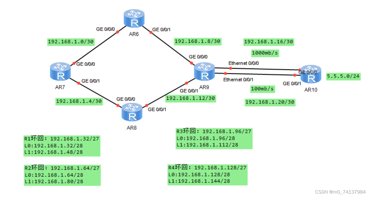
一、实验拓扑
二、实验要求 1.除了R5的环回地址固定5.5.5.0/24,其他网段基于192.168.1.0/24进行合理划分; 2.R1-R4每个路由器存在两个环回接口,模拟PC,地址也在192.168.1.0/24网络内; 3.R1-R4不能直接编写到达5.5.5.0/24的静态路由,但依然可以访问; 4.全网可达,尽量减少每台路由器路由条目数量,避免环路; 5.R4与R5间,正常1000M链路通信,故障时自动改为100M; 三、实验配置 步骤一:划分地址,对基于192.168.1.0/24的网段进行合理划分,然后配置IP地址 int g0/0/0 ip add 192.168.1.10 30 [R-GigabitEthernet0/0/0]quit [R]int g0/0/1 [3-GigabitEthernet0/0/1]ip add 192.168.1.13 30 步骤二:配置接口ip并用网段ip去ping测试 [R1]int g0/0/0 //进入接口 [R1-GigabitEthernet0/0/0]ip add 192.168.1.1 30 //配置接口IP(网关IP) [R1]int g0/0/1 [R1-GigabitEthernet0/0/1]ip add 192.168.1.5 30 [R2]int g0/0/0 [R2-GigabitEthernet0/0/0]ip add 192.168.1.2 30 [R2]int g0/0/1 [R2-GigabitEthernet0/0/1]ip add 192.168.1.9 30 [R3]int g0/0/0 [R3-GigabitEthernet0/0/0]ip add 192.168.1.6 30 [R3]int g0/0/1 [R3-GigabitEthernet0/0/1]ip add 192.168.1.13 30 [R4]int g0/0/0 [R4-GigabitEthernet0/0/0]ip add 192.168.1.10 30 [R4]int g0/0/1 [R4-GigabitEthernet0/0/1]ip add 192.168.1.14 30 [R4]int g0/0/2 [R4-GigabitEthernet0/0/2]ip add 192.168.1.17 30 [R4]int g4/0/0 [R4-GigabitEthernet4/0/0]ip add 192.168.1.21 30 [R5]int g0/0/0 [R5-GigabitEthernet0/0/0]ip add 192.168.1.18 30 [R5]int g0/0/1 [R5-GigabitEthernet0/0/1]ip add 192.168.1.22 30 [R5]int g0/0/2 [R5-GigabitEthernet0/0/2]ip add 192.168.1.193 27 步骤三:在R1 R2 R3 R4 R5上分别配置环回接口地址 int LoopBack0 [R-LoopBack0]ip add 192.168.1.69 28 步骤四:配置各自的路由地址 [R2]ip route-static 192.168.1.128 27 192.168.1.10 [R2]ip route-static 192.168.1.16 30 192.168.1.10 [R2]ip route-static 192.168.1.20 30 192.168.1.10 [R2]ip route-static 192.168.1.12.30 192.168.1.10 [R2]ip route-static 192.168.1.96 27 192.168.1.10 [R2]ip route-static 192.168.1.96 27 192.168.1.1 [R2]ip route-static 192.168.1.4 30 192.168.1.1 步骤五:路由汇总 将R1 R2 R3 R4的环回地址分别汇总,减少每台路由器路由条数数量 步骤六:配置缺省路由 [R1]ip route-static 0.0.0.0 0 192.168.1.2 [R1]ip route-static 0.0.0.0 0 192.168.1.16 [R2]ip route-static 0.0.0.0 0 192.168.1.10 [R3]ip route-static 0.0.0.0 0 192.168.1.14 [R4]ip route-static 0.0.0.0 0 192.168.1.16 步骤七:配置R4到R5的路由优先级,配置成为浮动路由 [R4]ip route-static 0.0.0.0 0 192.168.1.22 preference 61 [R5]Ip route-static 192.168.1.128 27 192.168.1.21 preference 61 [R5]ip route-static 192.168.1.12 30 192.168.1.21 preference 61 [R5]ip route-static 192.168.1.96 27 192.168.1.21 preference 61. [R5]ip route-static 192 168.1.4 30 192.168.1.21 preference 61 [R5]ip route-static 192.168.1.32 27 192.168.1.21 preference 61 [R5]ip route-static 192.168.1.0 30 192.168.1.21 preference 61 [R5]ip route-static 192.168.1.64 27 192.168.1.21 preference 61 [R5]ip route-static 192.168.1.8 30 192.168.1.21 preference 61 [R5]ip route-static 192.168.1.4 30 192.168.1.21 preference 61 步骤八:配置空接口 -- 当汇总地址和缺省路由同时存在,容易存在路由黑洞,形成环路,配置空接口可防此类环 [R1]ip route-static 192.168.1.32 27 NULL 0 //汇总地址IP,路由项匹配原则是按照最长掩码 匹配原则,当这个网段没有路由黑洞时,会进行精确匹配,不会丢入空接口 [R2]ip route-static 192.168.1.64 27 NULL 0 [R3]ip route-static 192.168.1.96 27 NULL 0 [R4]ip route-static 192.168.1.128 27 NULL 0 [R5]ip route-static 192.168.1.160 27 NULL 0 |
【本文地址】
今日新闻 |
推荐新闻 |