汇川伺服Modbus |
您所在的位置:网站首页 › 汇川伺服报警复位是那个参数 › 汇川伺服Modbus |
汇川伺服Modbus
|
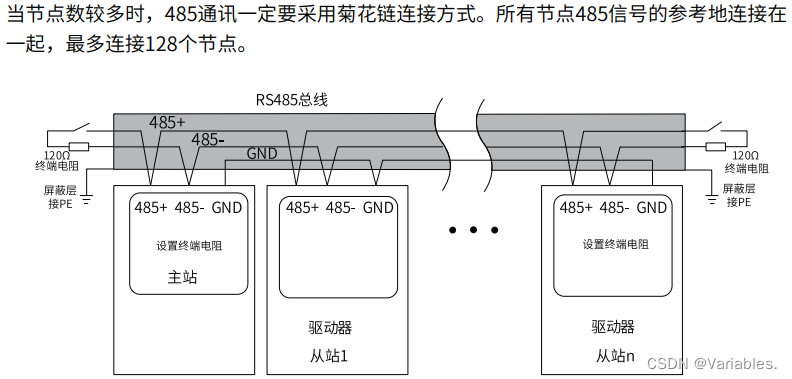
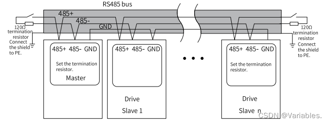
目录 Table of Content 1 前言 Preface 2 硬件配置 Hardware Configuration 3 通信数据帧结构 Data Frame Structure 3.1 读参数命令码0x03 Command code for reading parameter 0x03 3.1.1 通讯举例 Communication example 3.2 写参数命令码0x06/0x10 Command code for writing parameters 0x06/0x10 3.2.1 写16位参数命令码0x06 Command code for writing 16-bit parameters 0x06 3.2.1.1 0x06通讯举例 0x06 Communication example 3.2.2 写32位参数命令码0x10 Command code for writing 32-bit parameters 0x10 3.2.2.1 0x10通讯举例 0x10 Communication example 4 通信配置实例 Communication Configuration Instance 4.1 西门子 S7-200Smart Siemens S7-200Smart 4.1.1 通讯布线 Communication Wiring 4.1.2 伺服参数设置 Servo Parameter Settings 4.1.3 PLC程序示例 PLC Program Examples 1 前言 PrefaceModbus协议是应用于电子控制器上的一种通用语言。通过此协议,可以实现控制器相互之 间、控制器经由网络和其它设备之间的通信。它已经成为一种通用工业标准。基于这个通信协议,不同厂商生产的控制设备可以连成一个工业网络,进行集中监控。 The Modbus protocol is a common language applied to electronic controllers. Based on this protocol, controllers can communicate with each other and with other devices. This protocol has become a general industry standard. This communication protocol enables control devices produced by different manufacturers to be connected into an industrial network for centralized monitoring. 2 硬件配置 Hardware Configuration
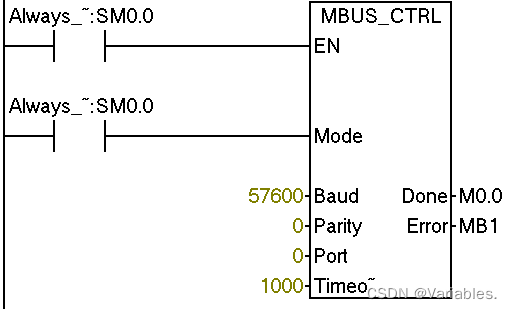
请求帧格式 Request frame format 值 Value描述 DescriptionADDR伺服轴地址:1~247 注:这里1~247为十进制数,需要转换为十六进制数 Servo axis address: 1 to 247. Note: 1 to 247 are decimal values which need to be converted into hexadecimal equivalents. CMD命令码:0x03 Command code: 0x03 DATA[0]寄存器起始地址(高8位):起始寄存器参数组号 如参数H06.11,06即为组号,即DATA[0]=0x06 注:这里06为十六进制数,不需进制转换 Register start address (eight high bits): parameter group number of the start register. Take H06.11 as an example, "06" is the group number, which means DATA[0] = 0x06. Note: In this example, "06" is a hexadecimal value that needs no conversion. DATA[1]寄存器起始地址(低8位):起始寄存器参数组内偏置 如参数H06.11,11为组内偏置。即DATA[1]= 0x0B 注:这里11为十进制数,需要转换为十六进制0x0B Register start address (eight low bits): offset within the parameter group of the start register. Take H06.11 as an example, "11" is the offset within the parameter group. That is, DATA [1] = 0x0B. Note: In this example, ''11" is a decimal value that needs to be converted into the hexadecimal equivalent 0x0B. DATA[2]读取参数数量的高8位N(H),十六进制 Read the eight high bits N (H) of the number of parameters (hexadecimal). DATA[3]读取参数数量的低8位N(L),十六进制 Read the eight low bits N (L) of the number of parameters (hexadecimal). CRCLCRC校验有效字节(低8位) CRC valid byte (low 8 bits). CRCHCRC校验有效字节(高8位) CRC valid byte (high 8 bits). 响应帧格式 Response frame format 值 Value描述 DescriptionADDR伺服轴地址,十六进制 Servo axis address, hexadecimal. CMD命令码:0x03 Command code: 0x03 DATALENGTH参数字节数,等于读取参数数量N×2 Number of parameter bytes, equal to reading the number of parameters N x 2. DATA[0]第一个寄存器参数的数据,高8位 Parameter data in the first register (eight high bits). DATA[1]第一个寄存器参数的数据,低8位 Parameter data in the first register (eight low bits). DATA[...]... DATA[N*2-2]第N个寄存器参数的数据,高8位 Parameter data in the Nth register (eight high bits). DATA[N*2-1]第N个寄存器参数的数据,低8位 Parameter data in the Nth register (eight low bits) CRCLCRC校验有效字节(低8位) CRC valid byte (low 8 bits). CRCHCRC校验有效字节(高8位) CRC valid byte (high 8 bits). 3.1.1 通讯举例 Communication example从伺服轴地址为01驱动器中,以H02.02为起始寄存器读取2个字长的数据 To read data with a length of two words by taking H02.02 as the start register in the drive whose servo axis address is 01. 主机发送请求帧 Master request frame 010302020002CRCLCRCH从机响应帧 Slave response frame 01030400010000CRCLCRCH该响应帧表示:从机返回2字长(4个字节)的数据,数据内容为0x0001,0x0000 The response frame indicates the slave returns data with a length of two words (four bytes), the content of which is 0x0001 and 0x0000. 3.2 写参数命令码0x06/0x10 Command code for writing parameters 0x06/0x10 3.2.1 写16位参数命令码0x06 Command code for writing 16-bit parameters 0x060x06请求帧格式 0x06 Request frame format 值 Value描述 DescriptionADDR伺服轴地址:1~247 注:这里1~247为十进制数,需要转换为十六进制数 Servo axis address: 1 to 247. Note: 1 to 247 are decimal values which need to be converted into hexadecimal equivalents. CMD命令码:0x06 Command code: 0x06 DATA[0]寄存器起始地址(高8位):起始寄存器参数组号 如写参数H06.11,06即为组号,即DATA[0]=0x06 注:这里06为十六进制数,不需进制转换 Register start address (eight high bits): parameter group number of the start register. Take H06.11 as an example, "06" is the group number, which means DATA[0] = 0x06. Note: In this example, "06" is a hexadecimal value that needs no conversion. DATA[1]寄存器起始地址(低8位):起始寄存器参数组内偏置 如写参数H06.11,11为组内偏置。即DATA[1]= 0x0B 注:这里11为十进制数,需要转换为十六进制0x0B Register start address (eight low bits): offset within the parameter group of the start register. Take H06.11 as an example, "11" is the offset within the parameter group, which means DATA[1] = 0x0B. Note: In this example, ''11" is a decimal value that needs to be converted into the hexadecimal equivalent 0x0B. DATA[2]写入寄存器数据高8位,十六进制。 Write the 8 high bits of register data (hexadecimal). DATA[3]写入寄存器数据低8位,十六进制。 Write the 8 low bits of register data (hexadecimal). CRCLCRC校验有效字节(低8位) CRC valid byte (low 8 bits). CRCHCRC校验有效字节(高8位) CRC valid byte (high 8 bits). 0x06响应帧格式 0x06 Response frame format 值 Value描述 DescriptionADDR伺服轴地址,十六进制 Servo axis address, hexadecimal. CMD命令码:0x06 Command code: 0x06 DATA[0]寄存器起始地址(高8位):起始寄存器参数组号 如写参数H06.11,06即为组号,即DATA[0]=0x06 注:这里06为十六进制数,不需进制转换 Register start address (eight high bits): parameter group number of the start register. Take H06.11 as an example, "06" is the group number, which means DATA[0] = 0x06. Note: In this example, "06" is a hexadecimal value that needs no conversion. DATA[1]寄存器起始地址(低8位):起始寄存器参数组内偏置 如写参数H06.11,11为组内偏置。即DATA[1]= 0x0B 注:这里11为十进制数,需要转换为十六进制0x0B Register start address (eight low bits): offset within the parameter group of the start register. Take H06.11 as an example, "11" is the offset within the parameter group, which means DATA[1] = 0x0B. Note: In this example, ''11" is a decimal value that needs to be converted into the hexadecimal equivalent 0x0B. DATA[2]写入寄存器数据高8位,十六进制。 Write the 8 high bits of register data (hexadecimal). DATA[3]写入寄存器数据低8位,十六进制。 Write the 8 low bits of register data (hexadecimal). CRCLCRC校验有效字节(低8位) CRC valid byte (low 8 bits). CRCHCRC校验有效字节(高8位) CRC valid byte (high 8 bits). 3.2.1.1 0x06通讯举例 0x06 Communication example将数据0x0001写入伺服轴地址为01的驱动器参数H02.02中 To write data 0x0001 to H02.02 in the drive whose servo axis address is 01: Master request frame 主机发送请求帧 Master request frame 010602020001CRCLCRCH从机响应帧 Slave response frame 010602020001CRCLCRCH该响应帧表示:伺服轴地址为01的驱动器参数H02.02写入数据0x0001 This response frame indicates 0x0001 has been written to H02.02 in the drive whose servo axis address is 01. 3.2.2 写32位参数命令码0x10 Command code for writing 32-bit parameters 0x100x10请求帧格式 0x10 Request frame format 值 Value描述 DescriptionADDR伺服轴地址:1~247 注:这里1~247为十进制数,需要转换为十六进制数 Servo axis address: 1 to 247. Note: 1 to 247 are decimal values which need to be converted into hexadecimal equivalents. CMD命令码:0x06 Command code: 0x06 DATA[0]寄存器起始地址(高8位):起始寄存器参数组号 如写参数H11.12,11即为组号,即DATA[0]=0x11 注:这里06为十六进制数,不需进制转换 Register start address (eight high bits): parameter group number of the start register. Take H11.12 as an example, "11" is the group number, which means DATA[0] = 0x11. Note: In this example, "06" is a hexadecimal value that needs no conversion. DATA[1]寄存器起始地址(低8位):起始寄存器参数组内偏置 如写参数H11.12, 12即为组内偏置,即DATA[1]=0x0C 注:这里11为十进制数,需要转换为十六进制0x0B Register start address (eight low bits): offset within the parameter group of the start register. Take H11.12 as an example, "12" is the offset within the parameter group, which means DATA[1] = 0x0C. Note: In this example, ''11" is a decimal value that needs to be converted into the hexadecimal equivalent 0x0B. DATA[2]写入参数数量高8位M(H):十六进制 例如只写H05.07,DATA[2]为00,DATA[3]为02,M=H0002 32位参数每个参数按2个word计算 Write the eight high bits M (H) of the number of parameters (hexadecimal. Take H05.07 as an example, DATA[2] is 00, DATA[3] is 02, and M is H0002. For 32-bit parameters, each parameter is calculated as two words. DATA[3]写入参数数量低8位M(L):十六进制 Write the eight low bits M (L) of the number of parameters (hexadecimal). DATA[4]写入寄存器的数据对应字节数M×2 例如单写H05.07,DATA[4]为H04 Write the number of bytes (M x 2) corresponding to the register data. Take H05.07 as an example, DATA[4] is H04. DATA[5]写入起始寄存器数据高8位,十六进制 Write the eight high bits of the start register data (hexadecimal). DATA[6]写入起始寄存器数据低8位,十六进制 Write the eight low bits of the start register data (hexadecimal). DATA[7]写入起始寄存器地址+1的数据高8位,十六进制 Write the eight high bits of the start register address +1 (hexadecimal). DATA[8]写入起始寄存器地址+1的数据低8位,十六进制 Write the eight low bits of the start register address +1 (hexadecimal). CRCLCRC校验有效字节(低8位) CRC valid byte (low 8 bits). CRCHCRC校验有效字节(高8位) CRC valid byte (high 8 bits). 0x10响应帧格式 0x10 Response frame format 值 Value描述 DescriptionADDR伺服轴地址,十六进制 Servo axis address, hexadecimal. CMD命令码:0x10 Command code: 0x10 DATA[0]寄存器起始地址(高8位):起始寄存器参数组内偏置 如写参数H11.12,则DATA[0]为0x11 Register start address (eight high bits): offset within the parameter group of the start register. Take H11.12 as an example, DATA[0] = 0x11. DATA[1]寄存器起始地址(低8位):起始寄存器参数组内偏置 如写参数H11.12,则DATA[1]为0x0C Register start address (eight low bits): offset within the parameter group of the start register. Take H11.12 as an example, DATA[1] = 0x0C. DATA[2]写入参数数量高8位M(H):十六进制 Write the eight high bits M (H) of the number of parameters (hexadecimal). DATA[3]写入参数数量低8位M(L):十六进制 Write the eight low bits M (L) of the number of parameters (hexadecimal). CRCLCRC校验有效字节(低8位) CRC valid byte (low 8 bits). CRCHCRC校验有效字节(高8位) CRC valid byte (high 8 bits). 3.2.2.1 0x10通讯举例 0x10 Communication example例如向“第1段移动位移H11.12”写入“0x12345678”的Modbus指令: For example, the Modbus command for writing 0x12345678 to H11.12 (Displacement 1) is as follows: 若H0C.26=1(低16位在前,高16位在后): If H0C.26 = 1 (Low 16 bits before high 16 bits): 0110110C00020456781234CRCLCRCH若H0C.26=0(高16位在前,低16位在后): If H0C-26 = 0 (High 16 bits before low 16 bits): 0110110C00020412345678CRCLCRCH 4 通信配置实例 Communication Configuration Instance通信概述 Communication Overview 本案例以写速度(H06.03)和读速度(H0B.00)为例说明 The writing speed (H06-03)and reading speed (H0B-00) are used for illustration. 参数 Parameters 数据类型 Data Type 读/写 R/W 最大值 Max 最小值 Min 单位 Unit H06.03有符号16位 Int16 读/写 R/W 6000-6000rpmH0B.00有符号16位 Int16 读 R 9999-9999rpm 4.1 西门子 S7-200Smart Siemens S7-200Smart 4.1.1 通讯布线 Communication Wiring西门子S7200 PLC Siemens S7200 PLC 驱动器侧CN3/CN4端子排序 CN3/CN4 Terminal Layout on Drive Side PLC 端口0-RS485 PLC PORT0-RS485 针脚号 Pin No. 信号名称 Signal Name 针脚号 Pin No. RS485+3RS485+4RS485-8RS485-5PE(屏蔽网层) PE (shield layer) 壳体 Enclosure PE(屏蔽网层) PE (shield layer) 壳体 Enclosure 4.1.2 伺服参数设置 Servo Parameter Settings参数 Parameter 设置值 Value 说明 Description 备注 Remarks H0C.001驱动器轴地址 Drive axis address -H0C.025串口波特率设置 Serial baud rate 5:57600bpsH0C.033Modbus数据格式 Modbus data format 3:无校验,1个停止位 3: No parity, 1 stop bit H0C.260Modbus通讯数据高低位顺序 Modbus communication data sequence 0:高十六位在前,低十六位 在后 1:低十六位在前,高十六位在后 0: High 16 bits before low 16 bits 1: Low 16 bits before high 16 bits 4.1.3 PLC程序示例 PLC Program Examples主站初始化 Master Initialize
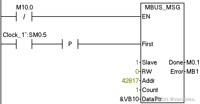
读取速度 Reading Speed 1秒钟读取一次速度(H0B.00) Read speed once per second(H0B.00) 地址计算伪代码 Address calculation pseudocode 如果 (十六进制转十进制(组号+00)+组内偏置>9999) { 十六进制转十进制(组号+00)+组内偏置+400001; } 否则 { 十六进制转十进制(组号+00)+组内偏置+40001; } if (Hexadecimal To Decimal(group number+00)+group offset>9999) { Hexadecimal To Decimal(group number+00)+group offset+400001; } else { Hexadecimal To Decimal(group number+00)+group offset+40001; }
写入速度 Write Speed
|


【本文地址】
今日新闻 |
推荐新闻 |