Designing for 200 BMEP and 22,000 Rpm |
您所在的位置:网站首页 › rc166 › Designing for 200 BMEP and 22,000 Rpm |
Designing for 200 BMEP and 22,000 Rpm
|
April 1, 2023 Kevin Cameron 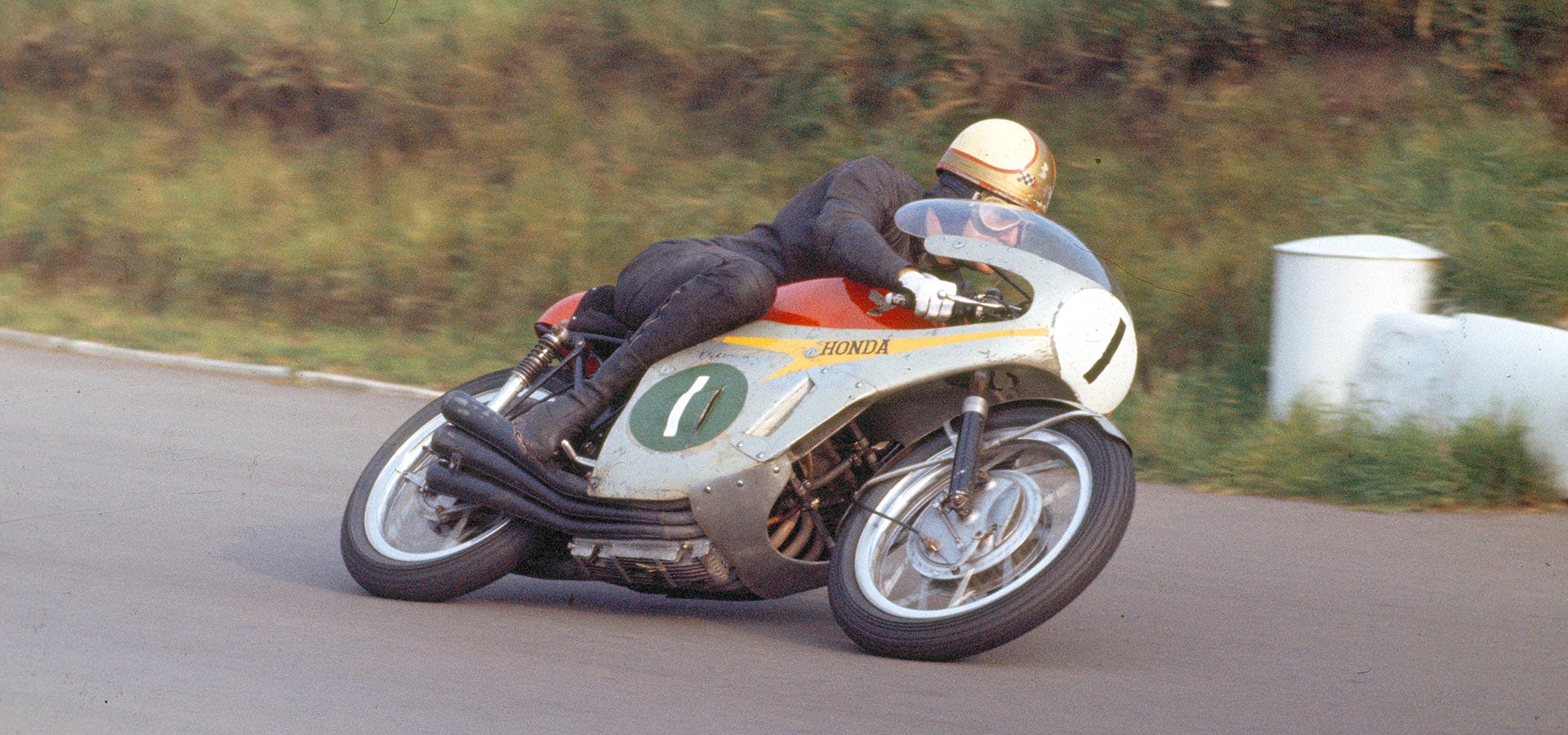 Honda’s mighty 66-hp, 250cc six-cylinder, 18,000-rpm RC166 was unbeatable with world champion rider Mike Hailwood, shown here in 1966 at Mallory Park. (B.R. Nicholls/Mortons Archive) Honda’s mighty 66-hp, 250cc six-cylinder, 18,000-rpm RC166 was unbeatable with world champion rider Mike Hailwood, shown here in 1966 at Mallory Park. (B.R. Nicholls/Mortons Archive) Fire-bombing destroyed Japan’s 66 largest cities and their industry during World War II. After the war, over 200 makers of light motorbikes sprang into being because such transportation could be quickly tooled for production. Only a few of the start-ups – those known for reliable, maintainable products – survived. By the late 1950s saturation of the domestic market imposed a choice: export or stagnate. 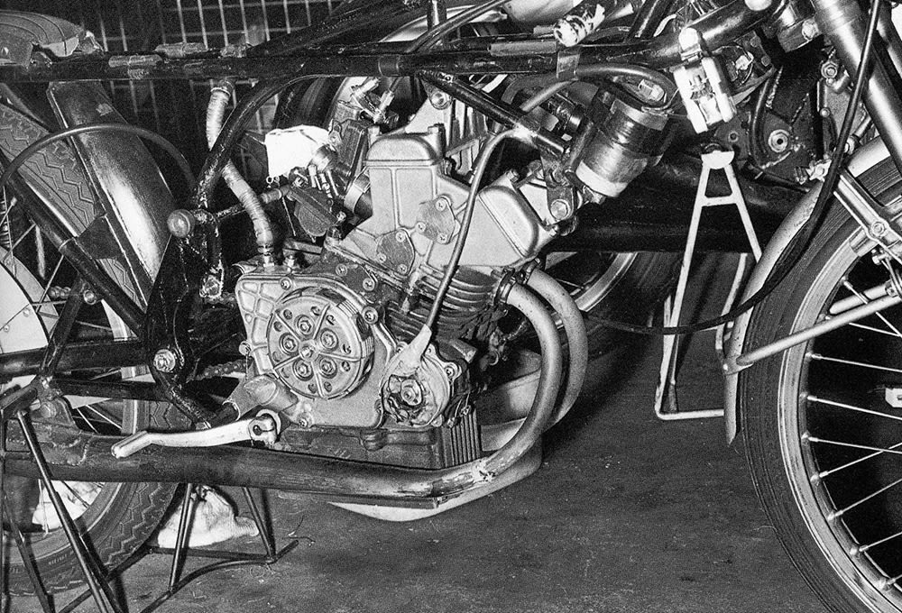 Honda design engineer Shoichiro Irimajiri’s masterpiece, the 50cc twin-cylinder, 21,500-rpm RC-115 put Honda in the vanguard of ICE technology. (Mick Woollett Archive; used by permission) Honda design engineer Shoichiro Irimajiri’s masterpiece, the 50cc twin-cylinder, 21,500-rpm RC-115 put Honda in the vanguard of ICE technology. (Mick Woollett Archive; used by permission) Only a few returning U.S. servicemen had ever heard of Honda motorcycles. Who would buy them? Soichiro Honda, a self-taught mechanic and former auto racer, knew that great names had been made through innovation and international racing success. On a 1950s tool-buying trip to Europe, he bought two racing machines — a German NSU and an Italian Mondial — for study in Japan. He committed his company to four-stroke engines and declared that it would compete in the Isle of Man TT road races that had shaped motorcycle development since 1907. Honda’s production motorcycles offered only a third of the specific power of the high-rpm racers he’d brought back from Europe. It was grist for Honda’s fast-growing and well-equipped R&D department. Their target: beat the Yamaha two-stroke bikes that dominated Japan’s “Volcano Race” held annually on a rough cinder track. For 1959 Honda engineers designed the RC-160, a four-stroke DOHC 250cc inline four-cylinder, generating 35 hp (26 kW) at 13,500 rpm and mounted transversely in the bike’s chassis. 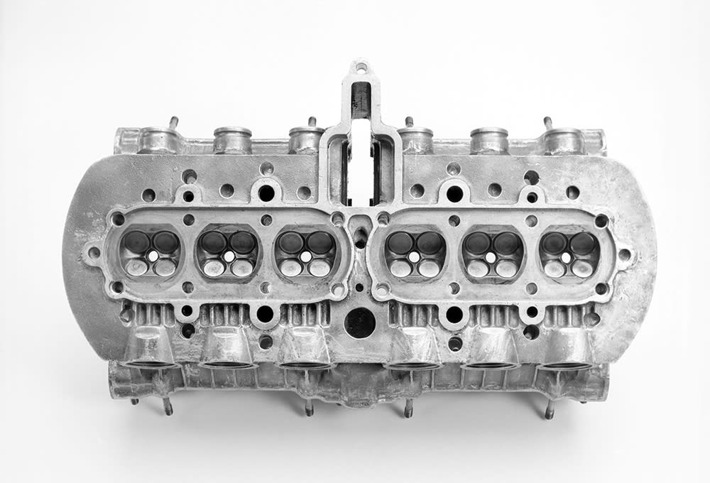 RC165 cylinder head showing combustion chamber geometry. Note tunnel for the camshaft gear drive on the intake side. (John Owens) RC165 cylinder head showing combustion chamber geometry. Note tunnel for the camshaft gear drive on the intake side. (John Owens) In Europe, the superior specific flow of a single intake valve in a hemispherical combustion chamber was unquestioned. However, the mass of that large single valve resulted in European race bike engines having as few as 300 revs between peak power and valve float. Every time the RC-160’s rear wheel left the bumpy track surface, its tach needle shot into the red, but the opposition’s two-strokes were unaffected. Honda’s young engineers needed a wider safety zone to avoid catastrophic valve failure. The solution they chose ignored the dogma that the flow coefficient of a single intake valve in a hemi chamber substantially exceeds that of a pair in a pentroof chamber. The engineers revived the old four-valve concept not for its airflow, but for its higher resistance to valve float. Years later, engineers would refer to “Duckworth’s Rule” named after Cosworth Engineering engine designer Keith Duckworth: By adopting four valves in place of two, important parameters are improved by a factor equal to the square root of two. Battle for BMEP and rpm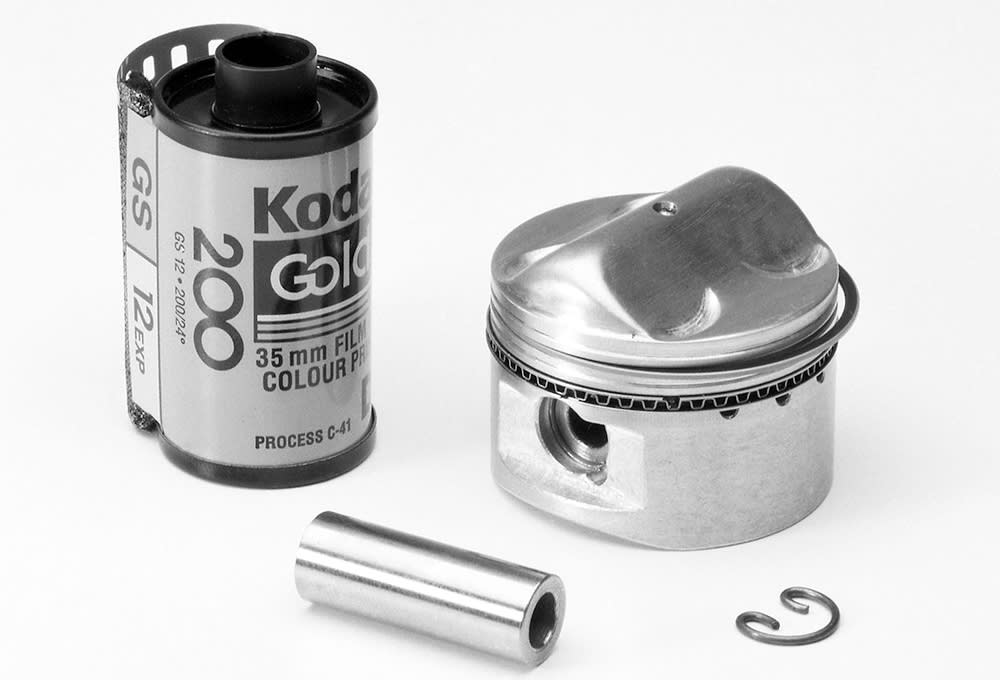 Grand Prix miniaturization: Tiny 39mm piston, pin and clip from the Honda 250cc RC165, next to a 35mm film canister for size comparison. (John Owens) Grand Prix miniaturization: Tiny 39mm piston, pin and clip from the Honda 250cc RC165, next to a 35mm film canister for size comparison. (John Owens) Honda entered the 1960s era of GP racing with three times the overrev margin of European competitors. If more airflow was needed, larger bores and shorter strokes could accommodate bigger valves. Honda’s successful RC-160 of 1959 was followed by later 250cc fours whose cylinders were inclined forward 30-35 degrees, increasing airflow over cooling fins between the intake and exhaust cam boxes. The RC-160’s original (and torsionally springy) towershaft-and-bevels cam drive was replaced by a central train of spur gears, located behind rather than between the cylinders to reduce engine width. Mercedes had used the same approach with their straight-eight F1 engine of 1953. A centrally located gear drive to the gearbox and camshafts cut the ‘vibrating length’ of the crankshaft in half. 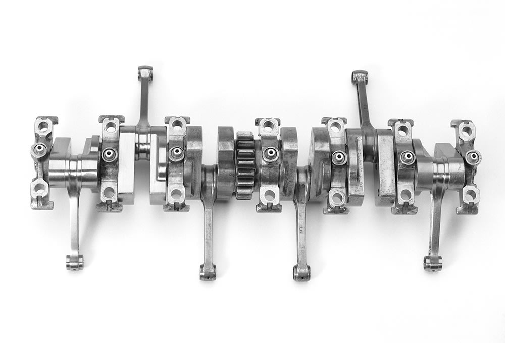 All crankshafts in Honda’s 1960s GP engines (RC165 six shown) were pressed together to allow use of one-piece connecting rods and main and crankpin rolling-element bearings. The central gear drove the clutch through a jackshaft. (John Owens) All crankshafts in Honda’s 1960s GP engines (RC165 six shown) were pressed together to allow use of one-piece connecting rods and main and crankpin rolling-element bearings. The central gear drove the clutch through a jackshaft. (John Owens) Honda won its first FIM Grand Prix championship in 1961 — the first of many. In 1962 the FIM added a 50cc class, won by Suzuki two-stroke single-cylinder racers for three years straight. Honda, its four-stroke reputation on the line, rose to the challenge. BMEP, or brake mean-effective pressure, is an IC engine’s stroke-averaged net combustion pressure — a figure of merit for cylinder filling and combustion efficiency. In best practice naturally aspirated four-strokes, peak power BMEP had, by 1960, reached a practical maximum of about 200 psi (1379 kPa). This compelled Honda to seek power by raising rpm capability through the shorter strokes of many small cylinders. Two-stroke rpm is limited by the difficulty of fitting the intake, compression, power and exhaust functions into only two piston strokes. As Honda increased rpm capability with more cylinders and shorter strokes, the two-stroke builders replied with increased trapping efficiency — learning to retain in the cylinders more of the charge blown through them during scavenging. The RM64 Suzuki that took the 1964 50cc world title needed 14,000 rpm to achieve 12.5 hp (9.3 kW), while Honda’s RC-112 twin, revving to 17,500 rpm, had replaced their 50cc single in late 1962. But four-stroke power was somehow not “scaling” properly; Honda’s 50cc BMEP was stuck in the 140s- only 70% of what other racing engines had achieved. What was missing? Tackling the variablesHonda’s early race engines had been designed by Tadashi Kume and Kimio Shinmura. The problem of beating the two-strokes in the 50cc class was given to 24-year-old Shoichiro Irimajiri, who had joined Honda after graduating from Tokyo University with an aeronautical engineering degree. “Iri’s” 1964 refinements to the existing 50cc twin helped beat Suzuki at the Japanese Grand Prix, while Suzuki retained the championship. Irimajiri faced these problems: Small cylinders lose a lot of heat from their unfavorable ratio of surface area to volume; The added surface area of traditional deep combustion chambers and tall piston domes further increased heat loss; Seeking power from ever-higher rpm drove up friction losses.Compression ratio in most of Honda’s racing engines had reached 12:1 by 1966. The easy way to raise compression was by raising piston dome heights. This increased the heat-gathering area exposed to combustion and transformed the chamber into a slow-burning thin lamina — the peel of half an orange. That required very early ignition timing that further increased heat loss. Yet Honda’s experiments with research engines had shown, by 1964, that combustion did not systematically fall behind even at engine speeds as high as 27,000 rpm. Irimajiri explored all variables, seeking any trend of performance improvement. He increased bore/stroke ratio from Honda’s usual 1.07 to 1.41 of his 1966 RC-149 five-cylinder 125cc engine, to make room for adequate valve sizes. He designed shallower combustion chambers and piston domes by radically reducing valve included angle. The early 250cc four-cylinder had a 76-degree included angle; the 1964 RC-113 50cc twin, 72 degrees. He now chose a much narrower 56 degrees. Because reduced valve included angle left less room for cooling fins between the cam boxes, more of the cooling task was transferred to the oil. In 1966 Honda’s four-, five-, and six-cylinder race bikes were given oil coolers. Attacking frictionIrimajiri attacked sources of friction in his new 50cc RC-115. Honda’s original 250cc GP fours were constructed much like Japanese production bike engines. A pressed-together crankshaft with full-circle flywheels turned on large roller main bearings. Bearing ODs were clamped between an upper and lower horizontally split crankcase, as were the gearbox shafts. Also similar to production, the crankcase closely encircled the crank’s flywheels. Holes in the lower case allowed spent oil to drain back to sump or scavenge pump below. The RC-115 no longer enclosed circular flywheels in a close-fitting horizontally split crankcase. Irimajiri switched from large diameter ball or roller mains to the smallest possible caged needle bearings, made as “pillow blocks” bolted to the underside of the upper crankcase/cylinder casting. The lower case, now having no structural function, became magnesium. Main bearing oiling came from a transverse gallery in the lower case, delivering to each main bearing by upward projections sealed by O-ring. Three benefits resulted: Removing the spinning crankshaft from any possibility of acting as a “viscometer,” shearing oil between itself and the nearby inner crankcase walls Minimizing resistance to the pumping of crankcase air between neighboring cylinders Minimizing the diameters of all bearingsThe aim of #3 above was to reduce the velocity at which bearing rolling elements “squished” through any oil film on their races, thereby reducing bearing friction torque. We’ve all driven at highway speed onto a thin layer of standing water: you feel the car decelerate as its “rollers” squirt the fluid ahead of them. Joe Craig, Norton’s 1930s racing engineer, noted that big-end roller bearing temperature rose much faster from too much oil than from too little. In examining a disassembled RC-165 250cc six-cylinder crankshaft, the author saw tiny out-pumping chevrons embossed into the ODs of main bearing needle cages. Such chevrons are often seen on oil seals. The crankshaft was radically altered. The previous full-circle webs were replaced by minimum-mass narrow rectangular bars. Each carried two cylindrical tungsten balance weights opposite the crankpin. Bearing learningsRadically low crankshaft polar moment gave these Honda GP engines their distinctive “yelping dogs” exhaust sound during warm up. When the mechanic (or an inexperienced rider) closed the throttle, the engine stopped almost instantly. Journalists during that era argued that the light cranks boosted acceleration but the real reasons are more interesting. Two experienced race team managers, the late Dick O’Brien of Harley-Davidson and Rob Muzzy of Superbike racing fame told the author that they could never get engines with light cranks to top-end properly at Daytona. A technical paper from Honda’s recent F1 experience (‘Development of Reciprocating Parts and Crankshaft in Honda’s Third Formula 1 Era,’ T.Gotou and N. Yanagisawa, Honda R&D Technical Review, 2009) explains. The engineers discovered that crankshaft torsional activity plus cyclic rpm variation could cause valve float to occur as much as 1600 rpm below the threshold found in rig testing. 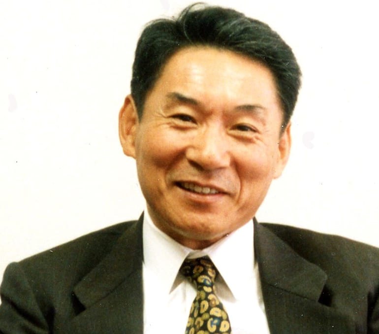 GP engine design leader Shoichiro Irimajiri went on to lead development of Honda production bikes then headed Honda’s Marysville, Ohio, assembly plant. He was later an executive with Sega. (courtesy S. Irimajiri) GP engine design leader Shoichiro Irimajiri went on to lead development of Honda production bikes then headed Honda’s Marysville, Ohio, assembly plant. He was later an executive with Sega. (courtesy S. Irimajiri) The great enemy of crankshafts is torsional vibration — cyclic twisting back-and-forth caused by the crank’s elasticity being excited by cylinder firing impulses. This is complicated if, as in all Honda GP race cranks of this period, it is pressed together. The torque capacity of the joints has limits. Mr. Honda believed rolling-element bearings to be essential at high rpm, but the 20,000 rpm Formula 1 plain bearing engines of the V-10 era refute this. All of the crankshafts in Honda’s 1960s GP engines were pressed together to allow use of one-piece connecting rods and main and crankpin rolling bearings. Another friction-reducing change made by Irimajiri was to move lateral location of the connecting rods from the big-end (rotating) to the small-end (oscillating). Irimajiri’s radical design changes were effective, enabling Honda rider Ralph Bryans to win the 1965 50cc Grand Prix championship. Iri’s success led to his next assignments: design an improved 125cc race engine (an in-line 5-cylinder, replacing the previous 4-cylinder) to parry Suzuki’s 1965 125 championship, and design a crank train for the 250cc six-cylinder 3RC-164. Since its introduction in late 1964, the Honda “six” had failed to stop Yamaha’s 1964-’65 two-stroke dominance of the 250cc class. These multi-cylinder cranks (save for the 50cc twins) continued the use of a central gear driving the clutch by a jackshaft and the cams by spur gears located behind the cylinders. Because the torque transmitted through right and left crank halves increased as it approached the central gear, shafts, crankpins, and their bearings also increased in diameter. In the six-cylinder cranks, three different crankpin diameters were provided, and the same for main bearings and shafts. All were supported by caged needle bearings. It remains normal to this day to reduce crank bearing size to a practical minimum because friction torque rises steeply with diameter. It’s likely that as smaller-diameter shafts were tested, fatigue failures appeared. This presented a choice; either stop short of such failures or upgrade crankshaft material. This “torque tailoring” of the pressed joints also required that the crank webs be of minimum mass, seeking to raise the torsional frequency of each half of the crank above excitation by the firing frequency. Aerospace materials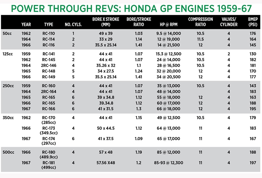 The engines listed in the table above show the Honda designers’ trend toward higher rpm to win the GP war against the two-strokes. (Cameron research) The engines listed in the table above show the Honda designers’ trend toward higher rpm to win the GP war against the two-strokes. (Cameron research) Irimajiri explained in an interview that the 1950-53 Korean War opened a high level of industrial cooperation between Japanese and U.S. companies. “When we had trouble with materials we went to GE or P&W in the USA (both are builders of aircraft turbine engines). They asked us, ‘what problems do you have?’ We explained and they introduced us to a very special steel, a new material they were using for turbine shafts. “We took samples home, went to Daido Steel or Nippon Special Steel, who analyzed it and then made the same for us,” he said. In reading about Honda’s GP engines, you will discover that specialists who have made modern replacement cranks for the revered 250cc six have said “We found in them materials unfamiliar to us.” The reason may have been ad hoc changes to established materials such as AISI 9310 to optimize them in vacuum-remelted form. Vacuum-remelted materials display increased fatigue resistance because the process greatly reduces the population of oxide inclusions (“stringers”) which may nucleate fatigue cracking. The aim of adopting such materials in highly stressed parts such as crankshaft and connecting rods was to allow further reductions of bearing diameters without penalty of failure. Piston innovations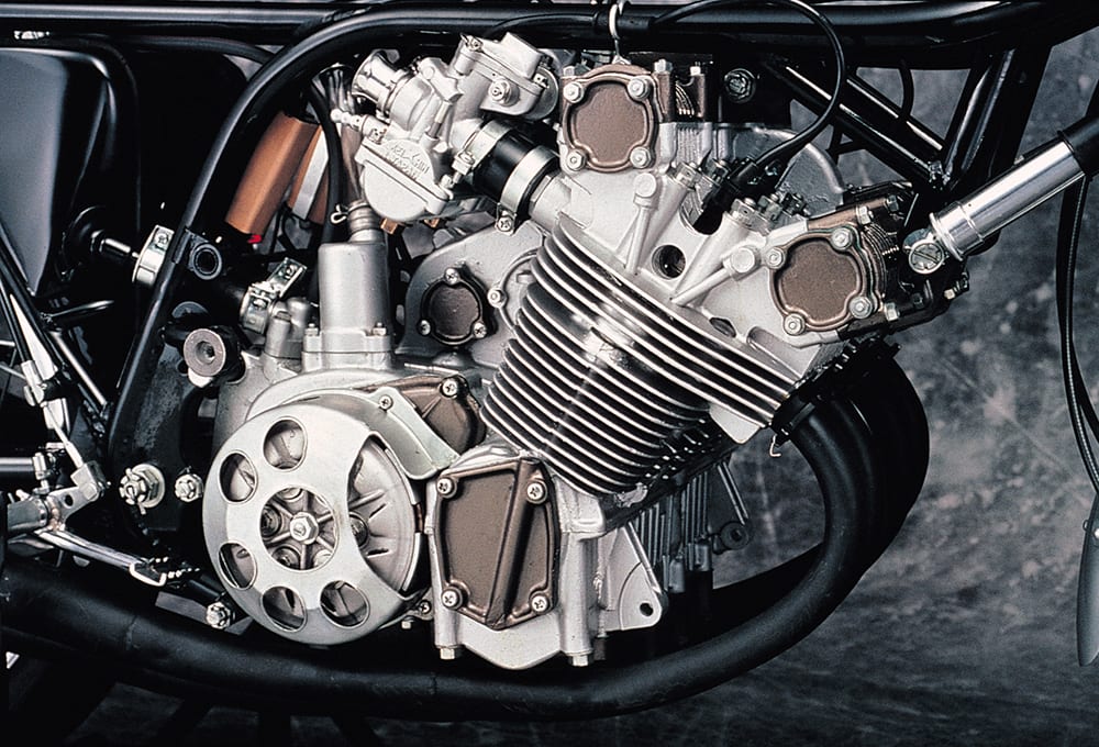 The 500cc four-cylinder RC-181 generated up to 93 hp but did not have the handling to match its power. (Honda) The 500cc four-cylinder RC-181 generated up to 93 hp but did not have the handling to match its power. (Honda) Because these engines were all air-cooled and internal oil flow was limited, piston cooling was accomplished mainly by intimate contact with cylinder walls. Piston axial length in Honda’s early 1960s 250cc fours was 1.24 times bore diameter, giving them a “1940 Chevy” look. Two compression rings and a single one-piece perforated oil scraper were provided. At the close of the 1967 season, piston length had dwindled to 65% of the bore with two rings — a single gas ring and sometimes a single taper-faced scraper very like those used in large U.S. radial aircraft engines. Honda’s 1962 race piston ODs were undercut in the ring belt and relieved over a large area of the sides. By comparison the pistons of 1967 appear engineered for top-to-bottom contact, much as two-stroke pistons were in the same time frame. Lighter pistons reduced bearing loads and fuller contact with the cylinder wall (especially in the ring belt) worked to reduce piston crown temperature and prevent ring sticking. Despite rumors of V8 wonders yet to come, Honda left motorcycle GP racing at the end of 1967 after racking up multiple world championships and helping to establish Honda as the leading motorcycle OEM. (Listen to a 250cc six-cylinder RC166 restored by Honda technicians run. ) Racing had indeed made Honda a household word worldwide. 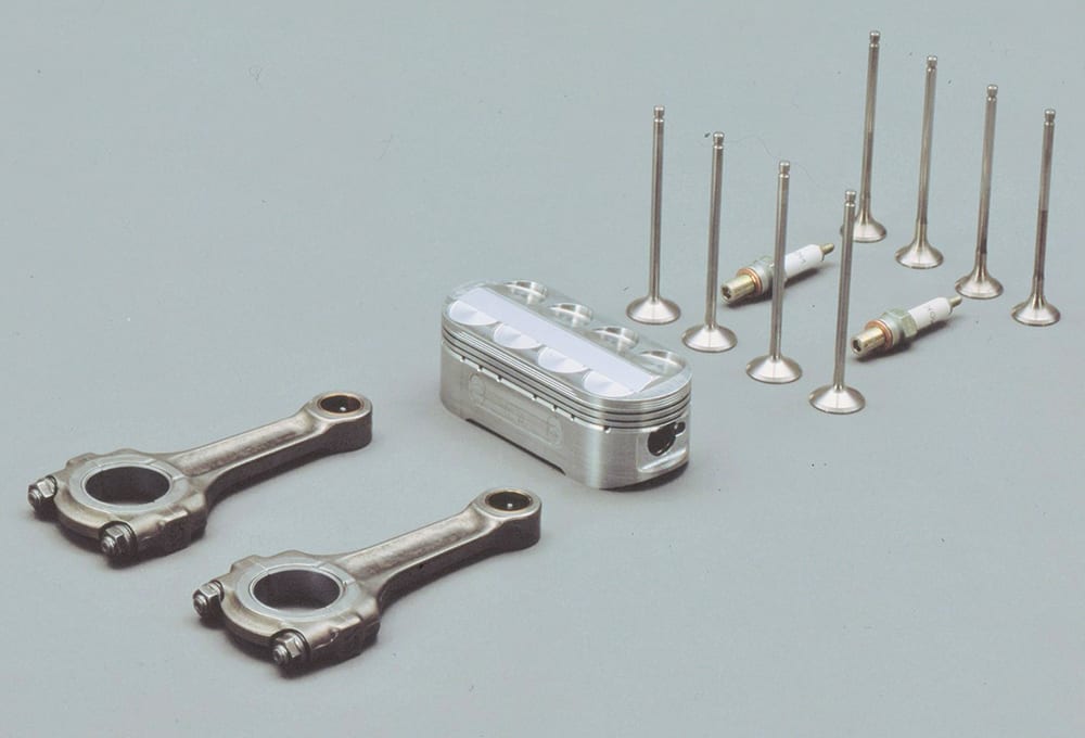 Oval pistons, each with a pair of con rods and octet of valves, was designed to give V8 breathing at over 20,000 rpm to the V4 NR500 racer. The components shown are from the NR750 street bike, a limited-production 1992 model. (Honda) Oval pistons, each with a pair of con rods and octet of valves, was designed to give V8 breathing at over 20,000 rpm to the V4 NR500 racer. The components shown are from the NR750 street bike, a limited-production 1992 model. (Honda) By 1975 two-strokes dominated every class in FIM GP racing. Honda was determined to reestablish four-stroke superiority. Because two-stroke BMEP was now approaching four-stroke levels, this proved beyond even Honda’s reach. Its solution was the bold oval-piston, 8-valves-per-cylinder V4 NR500, engineered to operate at near-double the rpm of the two-strokes (then nearing 12,000). This subjected its pistons to crack-producing peak accelerations 30% greater than the best F1 technology of the time could survive. A limited-production 750cc V4 street bike with oval pistons was later developed . The NR500 never won a single Grand Prix point but did ultimately reach 136 hp at 19,000 rpm. And having seen what was coming, Honda shifted its GP bike racing R&D to two-strokes, winning three Grands Prix in 1982 and making American rider Freddie Spencer 500cc world champion a year later on the three-cylinder NS3 two-stroke. In 2002 new FIM regulations began a process, completed in 2012, mandating four-stroke power in all motorcycle GP classes. Four-stroke racing development programs of the 1960s — at Honda in Japan and at Coventry-Climax and Cosworth in England — worked independently toward the eventual combination of four narrow-included-angle valves above an essentially flat-topped piston. What worked in racing also turned out to provide efficient combustion for the majority of today’s production auto, light truck and motorcycle engines. Kevin Cameron has been analyzing motorcycle technology for 50 years as a columnist in Cycle and Cycle World magazines. He is the author of the books, "The Grand Prix Motorcycle" and "Classic Motorcycle Race Engines." Topics: Bearings Cams Clutches Combustion and combustion processes Combustion chambers Connecting rods Crankcases Crankshafts Engine components Engine cylinders Engine mechanical components Engine/Powertrain Engines Internal combustion engines Joining & Assembly Mechanical Components Motion Control Parts Pistons Power Transmission Powertrains Racing engines Throttles Transmissions More From SAE Media Group Mobility Engineering GM Puts Its New Z06 Corvette V8 on a Different Plane Mobility Engineering Could This Infinitely Variable Compression Mechanism Be the Next Piston Engine Game-Changer? Mobility Engineering Could This Infinitely Variable Compression Mechanism Be the Next Piston Engine Game-Changer?  Mobility Engineering Chevrolet Delivers a Bombshell with First-Ever 4-Cylinder for Fullsize Pickups Mobility Engineering Chevrolet Delivers a Bombshell with First-Ever 4-Cylinder for Fullsize Pickups  Mobility Engineering Mercedes-AMG Extracts World-Record Power from New Four-Cylinder Engine Mobility Engineering Mercedes-AMG Extracts World-Record Power from New Four-Cylinder Engine  More Mobility Engineering GM details Corvette’s new and mighty LT6 V8 More Mobility Engineering GM details Corvette’s new and mighty LT6 V8  Mobility Engineering New Chevy Corvette ZR1’s LT5 V8: 2 Hp per Cubic Inch Mobility Engineering New Chevy Corvette ZR1’s LT5 V8: 2 Hp per Cubic Inch  Mobility Engineering Ford ‘Cranks’ It up with Another Big V8 for Mustang Mobility Engineering Ford ‘Cranks’ It up with Another Big V8 for Mustang  Mobility Engineering The IC Future Points to More Downsizing, Lean Mixtures Mobility Engineering The IC Future Points to More Downsizing, Lean Mixtures  Mobility Engineering Isuzu Simplifies Fuel Changeovers Mobility Engineering Isuzu Simplifies Fuel Changeovers  Mobility Engineering Engineering Artifact: Ford Mustang Boss 351 V10 Concept Mobility Engineering Engineering Artifact: Ford Mustang Boss 351 V10 Concept  Tech Briefs A New, Highly Improved Two-Cycle Engine Tech Briefs A New, Highly Improved Two-Cycle Engine  Mobility Engineering Is the Camshaft Being Timed Out? Mobility Engineering Is the Camshaft Being Timed Out?  Mobility Engineering 2020 Ford Super Duty Debuts All-New 7.3-Liter Pushrod V8, 10-Speed Automatic Mobility Engineering 2020 Ford Super Duty Debuts All-New 7.3-Liter Pushrod V8, 10-Speed Automatic  Mobility Engineering Spawning an All-New Gasoline Engine, Stellantis’ Hurricane Is Coming Mobility Engineering Spawning an All-New Gasoline Engine, Stellantis’ Hurricane Is Coming  Mobility Engineering 2022 Nissan Rogue Gets a VC Turbo Triple Mobility Engineering 2022 Nissan Rogue Gets a VC Turbo Triple  Mobility Engineering Sunset for the American V8 Mobility Engineering Sunset for the American V8  Mobility Engineering Caterpillar Unveils New C13D Off-Highway Engine Platform Mobility Engineering Caterpillar Unveils New C13D Off-Highway Engine Platform  Mobility Engineering GM Adopts Advanced Cylinder Deactivation for 2019 Chevy Silverado V8s Mobility Engineering GM Adopts Advanced Cylinder Deactivation for 2019 Chevy Silverado V8s  Mobility Engineering Unique Helmholtz Induction Feeds 2023 Corvette Z06 Mobility Engineering Unique Helmholtz Induction Feeds 2023 Corvette Z06  Mobility Engineering Porsche Partners to Develop 3D-Printed Pistons Mobility Engineering Porsche Partners to Develop 3D-Printed Pistons   Automotive Engineering Magazine Automotive Engineering Magazine This article first appeared in the April, 2023 issue of Automotive Engineering Magazine. Read more articles from this issue here. Read more articles from the archives here.
|
【本文地址】
今日新闻 |
推荐新闻 |