Keil下,基于STM32F103单片机的按键中断的几种LED实例 |
您所在的位置:网站首页 › keil流水灯控制速度 › Keil下,基于STM32F103单片机的按键中断的几种LED实例 |
Keil下,基于STM32F103单片机的按键中断的几种LED实例
|
Keil下,基于STM32F103单片机的按键中断的几种LED实例(流水、奇亮偶灭等)
这里是通过实验室的单片机实现的(皮赛公司的) 由于Keil版本的问题,5.15版本以下的版本使用C/C++开发单片机需要在option for target里的C/C++栏里对标准固件库进行宏定义(USE_STDPERIPH_DRIVER),不然无法识别stm32f10x.h的头文件。 新建工程、选择stm32f103zc芯片,勾选core,startup,framework,rcc,gpio,然后添加C源文件。下面是源码。 ****1、拨动实验箱上的拨码开关 DIP0、 DIP1、 DIP2、 DIP3 、 DIP4、 DIP5、 DIP6、DIP7 来控制对应的 LED 灯 D0、 D1、 D2、 D3 ,D4、 D5、D6、 D7 的亮灭。 #include"stm32f10x.h" #define ON Bit_SET //GPIO的布尔变量,用于GPIO_WriteBit函数 #define OFF Bit_RESET //GPIO的布尔变量,用于GPIO_WriteBit函数 #define LED0(x) GPIO_WriteBit(GPIOG, GPIO_Pin_11, x) #define LED1(x) GPIO_WriteBit(GPIOG, GPIO_Pin_10, x) #define LED2(x) GPIO_WriteBit(GPIOG, GPIO_Pin_9, x) #define LED3(x) GPIO_WriteBit(GPIOD, GPIO_Pin_7, x) #define LED4(x) GPIO_WriteBit(GPIOG, GPIO_Pin_3, x) #define LED5(x) GPIO_WriteBit(GPIOG, GPIO_Pin_2, x) #define LED6(x) GPIO_WriteBit(GPIOD, GPIO_Pin_13, x) #define LED7(x) GPIO_WriteBit(GPIOD, GPIO_Pin_12, x) #define DIP0 GPIO_ReadInputDataBit(GPIOE,GPIO_Pin_4) #define DIP1 GPIO_ReadInputDataBit(GPIOE,GPIO_Pin_5) #define DIP2 GPIO_ReadInputDataBit(GPIOC,GPIO_Pin_14) #define DIP3 GPIO_ReadInputDataBit(GPIOC,GPIO_Pin_15) #define DIP4 GPIO_ReadInputDataBit(GPIOF,GPIO_Pin_0) #define DIP5 GPIO_ReadInputDataBit(GPIOF,GPIO_Pin_1) #define DIP6 GPIO_ReadInputDataBit(GPIOF,GPIO_Pin_2) #define DIP7 GPIO_ReadInputDataBit(GPIOF,GPIO_Pin_3) void GPIO_Configuration(void); void DIP_Init(void); int main(void) { GPIO_Configuration(); DIP_Init(); while(1) { if(DIP0==1) { LED0(ON); }else LED0(OFF); if(DIP1==1) { LED1(ON); }else LED1(OFF); if(DIP2==1) { LED2(ON); }else LED2(OFF); if(DIP3==1) { LED3(ON); }else LED3(OFF); if(DIP4==1) { LED4(ON); }else LED4(OFF); if(DIP5==1) { LED5(ON); }else LED5(OFF); if(DIP6==1) { LED6(ON); }else LED6(OFF); if(DIP7==1) { LED7(ON); }else LED7(OFF); } } void DIP_Init(void) { GPIO_InitTypeDef GPIO_InitStructure; RCC_APB2PeriphClockCmd(RCC_APB2Periph_GPIOE | RCC_APB2Periph_GPIOC | RCC_APB2Periph_GPIOF, ENABLE);//使能PA,PF端口时钟 GPIO_InitStructure.GPIO_Pin = GPIO_Pin_4 | GPIO_Pin_5 ; GPIO_InitStructure.GPIO_Mode = GPIO_Mode_IPD; //设置成上拉输入 GPIO_Init(GPIOE, &GPIO_InitStructure); GPIO_InitStructure.GPIO_Pin = GPIO_Pin_14 | GPIO_Pin_15 ; GPIO_InitStructure.GPIO_Mode = GPIO_Mode_IPD; //设置成上拉输入 GPIO_Init(GPIOC, &GPIO_InitStructure); GPIO_InitStructure.GPIO_Pin = GPIO_Pin_0 | GPIO_Pin_1 | GPIO_Pin_2 | GPIO_Pin_3 ; GPIO_InitStructure.GPIO_Mode = GPIO_Mode_IPD; //设置成上拉输入 GPIO_Init(GPIOF, &GPIO_InitStructure); } void GPIO_Configuration(void) { GPIO_InitTypeDef GPIO_InitStructure; //按键初始化函数 RCC_APB2PeriphClockCmd(RCC_APB2Periph_GPIOG|RCC_APB2Periph_GPIOD, ENABLE);//使能PA,PB,PC,PG,PF端口时钟 GPIO_InitStructure.GPIO_Pin = GPIO_Pin_11 | GPIO_Pin_10 | GPIO_Pin_9 | GPIO_Pin_2 | GPIO_Pin_3; GPIO_InitStructure.GPIO_Mode = GPIO_Mode_Out_PP; //推挽输出 GPIO_InitStructure.GPIO_Speed = GPIO_Speed_50MHz; //IO口速度为50MHz GPIO_Init(GPIOG, &GPIO_InitStructure); GPIO_ResetBits(GPIOC,GPIO_Pin_11 | GPIO_Pin_10 | GPIO_Pin_7 | GPIO_Pin_9 | GPIO_Pin_2 | GPIO_Pin_3);//LED1,LED2,LED3,LED4,LED5 GPIO_InitStructure.GPIO_Pin = GPIO_Pin_7 |GPIO_Pin_12 | GPIO_Pin_13; GPIO_InitStructure.GPIO_Mode = GPIO_Mode_Out_PP; //推挽输出 GPIO_InitStructure.GPIO_Speed = GPIO_Speed_50MHz; //IO口速度为50MHz GPIO_Init(GPIOD, &GPIO_InitStructure); //根据设定参数初始 GPIO_ResetBits(GPIOD, GPIO_Pin_7 |GPIO_Pin_12|GPIO_Pin_13); //LED6,LED7 }频率设置为8MHZ,creat HEX files,链接然后编译。 将 USB 线一端连接至计算机,一端连接至实验箱 USB 调试口。 打开 Keil-MDK,设置好 J-Link 下载模式。 FLASH->configure flash tools->Debug,选择 J-Link/J-trace Cortex。 |
 点击Settings,进行设置。
  点击Utilities :选择J-LINK/J-Trace cortex。
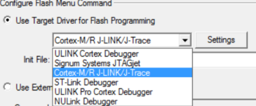 然后点击Settings,进行下图设置。
  插上电源线和JTAG转USB下载线,打开试验箱上开关,将BOOT0和BOOT1置零,并且按下复位键。点击下载按钮下载程序下好程序后点击仿真按钮 ,然后点击全速运行按钮 ,就可以在实验箱上看到对应的实验现象了。
 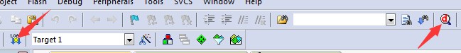 下面是定义了流水灯,奇数灯,偶数灯亮等的源代码 实现流水灯: 在上述代码预编译当中进行延时子程序的函数声明,然后将延时函数添加到代码中。将流水灯程序写到主函数当中,这里是用DIPO0控制流水灯。 奇数灯亮(偶数灯亮同理,改一下LED口就行)
【本文地址】
今日新闻 |
推荐新闻 |