TI DSP 28335 看门狗(WatchDog)及通过看门狗实现中断 |
您所在的位置:网站首页 › dsp中断响应时间 › TI DSP 28335 看门狗(WatchDog)及通过看门狗实现中断 |
TI DSP 28335 看门狗(WatchDog)及通过看门狗实现中断
|
文章目录
前言1 看门狗(监控芯片)2 相关寄存器2.1 WDCR看门狗控制寄存器2.2 WDCNTR看门狗计数器寄存器2.3 WDKEY看门狗复位寄存器2.4 SCSR系统控制和状态寄存器
3 看门狗电路4 看门狗例程例程功能描述将中断向量表的WAKEINT指向ISR:wakeint_isr使能看门狗中断输入安全秘钥,重置看门狗计数器使能看门狗(未分频)
5 看门狗中断响应时间分析5.1 看门狗计数时钟不分频5.2 看门狗计数时钟64分频
总结
前言
随开发板带的教程并没有给出WatchDog的解释和例程。 通过TI给出的源码结合调试开发板,正式看懂WatchDog。 特此记录,加深印象~ 1 看门狗(监控芯片)在由单片机构成的微型计算机系统中,由于单片机的工作常常会受到来自外界电磁场的干扰,造成各种寄存器和内存的数据混乱,会导致程序指针错误,不在程序区,取出错误的程序指令等,都有可能会陷入死循环,程序的正常运行被打断,由单片机控制的系统无法继续正常工作,导致整个系统的陷入停滞状态,发生不可预料的后果。 看门狗,又叫 WatchDog,从本质上来说就是一个定时器电路,一般有一个输入和一个输出,其中输入叫做喂狗,输出一般连接到另外一个部分的复位端,一般是连接到单片机。 看门狗的功能是定期查看芯片内部的情况,一旦发生错误就向芯片发出重启信号。看门狗命令在程序的中断中拥有最高的优先级。 2 相关寄存器 2.1 WDCR看门狗控制寄存器
当复位RST或者正确的秘钥WDKEY会重置看门狗计数器。 4 看门狗例程TI官网的例程如下: //########################################################################### // // FILE: Example_2833xWatchdog.c // // TITLE: DSP2833x Watchdog interrupt test program. // // ASSUMPTIONS: // // This program requires the DSP2833x header files. // // DESCRIPTION: // // This program exercises the watchdog. // // First the watchdog is connected to the WAKEINT interrupt of the // PIE block. The code is then put into an infinite loop. // // The user can select to feed the watchdog key register or not // by commenting one line of code in the infinite loop. // // If the watchdog key register is fed by the ServiceDog function // then the WAKEINT interrupt is not taken. If the key register // is not fed by the ServiceDog function then WAKEINT will be taken. // // Watch Variables: // LoopCount for the number of times through the infinite loop // WakeCount for the number of times through WAKEINT // //########################################################################### // $TI Release: 2833x/2823x Header Files and Peripheral Examples V133 $ // $Release Date: June 8, 2012 $ //########################################################################### #include "DSP2833x_Device.h" // Headerfile Include File #include "DSP2833x_Examples.h" // Examples Include File // Prototype statements for functions found within this file. interrupt void wakeint_isr(void); // Global variables for this example Uint32 WakeCount; Uint32 LoopCount; void main(void) { // Step 1. Initialize System Control: // PLL, WatchDog, enable Peripheral Clocks // This example function is found in the DSP2833x_SysCtrl.c file. InitSysCtrl(); // Step 2. Initalize GPIO: // This example function is found in the DSP2833x_Gpio.c file and // illustrates how to set the GPIO to it's default state. // InitGpio(); // Skipped for this example // Step 3. Clear all interrupts and initialize PIE vector table: // Disable CPU interrupts DINT; // Initialize PIE control registers to their default state. // The default state is all PIE interrupts disabled and flags // are cleared. // This function is found in the DSP2833x_PieCtrl.c file. InitPieCtrl(); // Disable CPU interrupts and clear all CPU interrupt flags: IER = 0x0000; IFR = 0x0000; // Initialize the PIE vector table with pointers to the shell Interrupt // Service Routines (ISR). // This will populate the entire table, even if the interrupt // is not used in this example. This is useful for debug purposes. // The shell ISR routines are found in DSP2833x_DefaultIsr.c. // This function is found in DSP2833x_PieVect.c. InitPieVectTable(); // Interrupts that are used in this example are re-mapped to // ISR functions found within this file. EALLOW; // This is needed to write to EALLOW protected registers PieVectTable.WAKEINT = &wakeint_isr; EDIS; // This is needed to disable write to EALLOW protected registers // Step 4. Initialize all the Device Peripherals: // This function is found in DSP2833x_InitPeripherals.c // InitPeripherals(); // Not required for this example // Step 5. User specific code, enable interrupts: // Clear the counters WakeCount = 0; // Count interrupts LoopCount = 0; // Count times through idle loop // Connect the watchdog to the WAKEINT interrupt of the PIE // Write to the whole SCSR register to avoid clearing WDOVERRIDE bit EALLOW; SysCtrlRegs.SCSR = BIT1; EDIS; // Enable WAKEINT in the PIE: Group 1 interrupt 8 // Enable INT1 which is connected to WAKEINT: // PieCtrlRegs.PIECTRL.bit.ENPIE = 1; // Enable the PIE block PieCtrlRegs.PIEIER1.bit.INTx8 = 1; // Enable PIE Gropu 1 INT8 IER |= M_INT1; // Enable CPU int1 EINT; // Enable Global Interrupts // Reset the watchdog counter ServiceDog(); // Enable the watchdog EALLOW; SysCtrlRegs.WDCR = 0x0028; EDIS; // Step 6. IDLE loop. Just sit and loop forever (optional): for(;;) { LoopCount++; // Uncomment ServiceDog to just loop here // Comment ServiceDog to take the WAKEINT instead // ServiceDog(); } } // Step 7. Insert all local Interrupt Service Routines (ISRs) and functions here: // If local ISRs are used, reassign vector addresses in vector table as // shown in Step 5 interrupt void wakeint_isr(void) { WakeCount++; // Acknowledge this interrupt to get more from group 1 PieCtrlRegs.PIEACK.all = PIEACK_GROUP1; } //=========================================================================== // No more. //=========================================================================== 例程功能描述LoopCount 计数for循环次数 WakeCount 计数WAKEINT中断触发的次数 如果不屏蔽ServiceDog();,即输入正确秘钥,则看门狗不会触发,WakeCount 并不会递增 for(;;) { LoopCount++; // Uncomment ServiceDog to just loop here // Comment ServiceDog to take the WAKEINT instead ServiceDog(); }例程总体思路同中断处理,此处只介绍和WatchDog相关的关键步骤,注释如下: 将中断向量表的WAKEINT指向ISR:wakeint_isr EALLOW; // This is needed to write to EALLOW protected registers PieVectTable.WAKEINT = &wakeint_isr; EDIS; // This is needed to disable write to EALLOW protected registers 使能看门狗中断 EALLOW; SysCtrlRegs.SCSR = BIT1; EDIS; 输入安全秘钥,重置看门狗计数器 void ServiceDog(void) { EALLOW; SysCtrlRegs.WDKEY = 0x0055; SysCtrlRegs.WDKEY = 0x00AA; EDIS; } 使能看门狗(未分频) EALLOW; SysCtrlRegs.WDCR = 0x0028; EDIS; 5 看门狗中断响应时间分析WDCR的WDPS可以配置看门狗计数时钟频率。 OSCCLK为晶振频率30MHz,通过PLL 5倍频得到系统时钟频率150MHz. 5.1 看门狗计数时钟不分频当WDPS为000或001时,不分频。 EALLOW; SysCtrlRegs.WDCR = 0x0028; EDIS;此时看门狗中断响应时间最短,为 1/(30M/512)*2^8S=1/(30/512)*0.256mS=4.37ms理论系统时钟周期为 5*512*256=655360通过CCS 6测得系统时钟周期为655381,符合。 5.2 看门狗计数时钟64分频当WDPS为111时,64分频。 EALLOW; SysCtrlRegs.WDCR = 0x002f; EDIS;此时看门狗中断响应时间最长,为 1/(30M/512/64)*2^8S=1/(30/512/64)*0.256mS=279.62ms理论系统时钟周期为 5*512*64*256=41943040通过CCS 6测得系统时钟周期为41943060,符合。 总结第37篇 博客阅读量过2W 个人水平有限,有问题欢迎各位大神批评指正! |
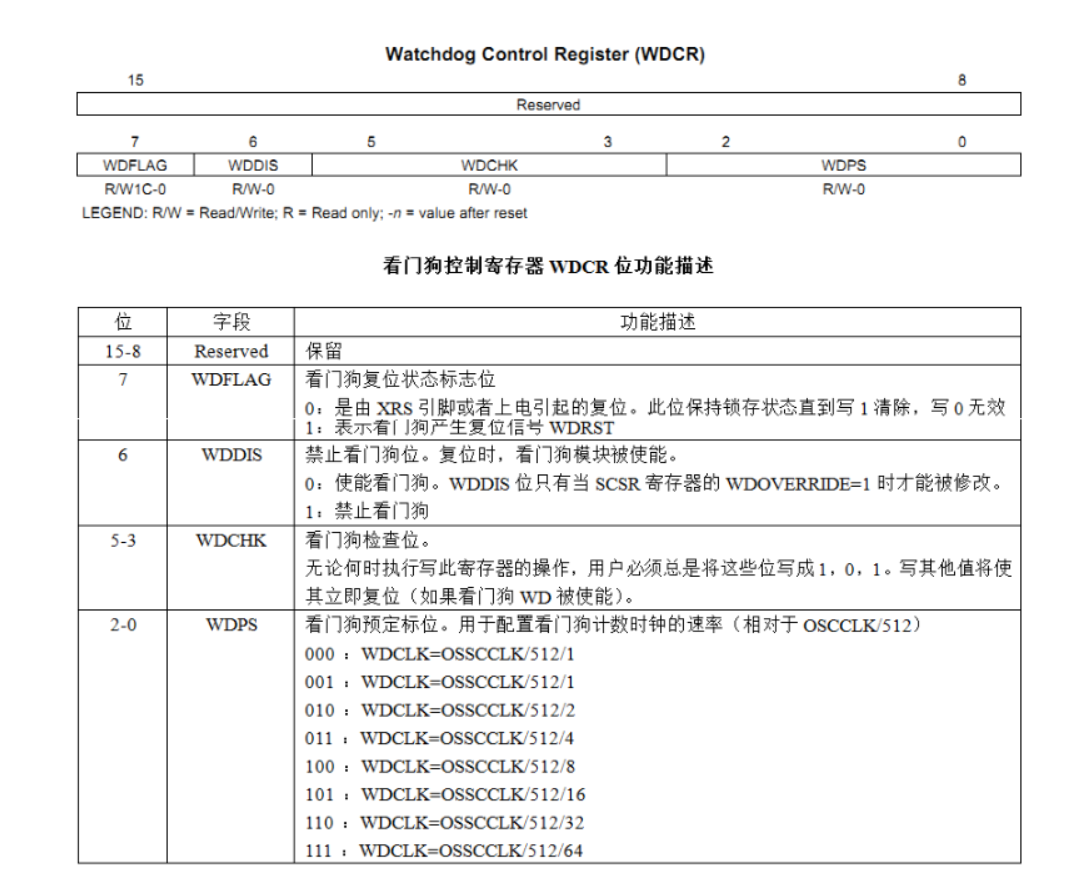 WDPS:决定看门狗计数时钟频率 WDDIS:决定看门狗的使能 WDCHK:应为101
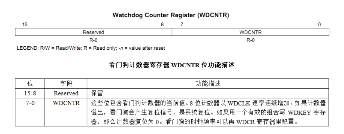 WDCNTR:看门狗计数器当前值
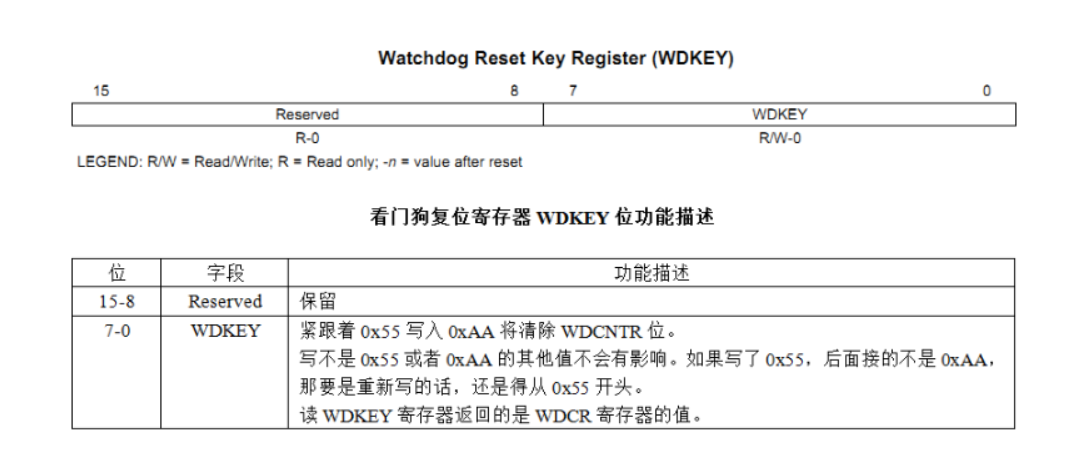 WDKEY:写0x55+0xAA会清除WDCNTR,即重置计数器
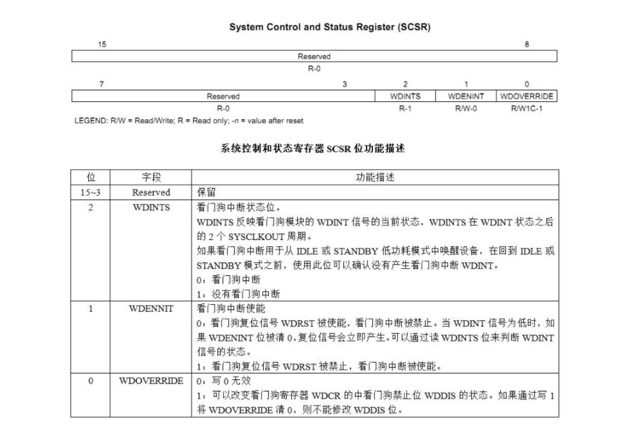 WDENNIT:看门狗中断使能。为0时为看门狗复位,为1时为看门狗中断。
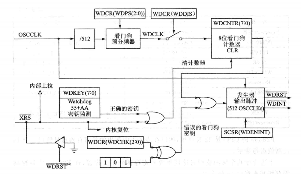 OSCCLK经分频和WDCR分频后,若WDDIS为0,则看门狗计数器工作。当没有正确的安全狗秘钥,计数器计满后溢出可产生输出512个OSCCLK时钟的脉冲信号。该信号作为复位信号WDRST还是中断信号WDINT由SCSR的WDENNIT决定。
【本文地址】