|
一、简介
在传统的自动化生产尺寸测量中,常用的方法是利用卡尺或千分尺对被测工件的某个参数进行多次测量,并取这些测量值的平均值。然而,这些传统的检测设备或手动测量方法存在着一些问题:测量精度不高、测量速度缓慢,以及测量数据无法及时处理等。这些局限性导致无法满足大规模自动化生产的需求。
相比之下,基于机器视觉技术的尺寸测量方法具有以下优点:
成本低: 机器视觉设备相对传统设备成本较低,而且在某些情况下,可以使用普通的摄像头。精度高: 机器视觉系统能够提供高精度的测量结果,可达到微米级别的精度。非接触性: 不需要物理接触被测量物体,避免了对物体的损伤或变形。实时性: 可以实时获取测量结果,提高生产效率并及时发现问题。灵活性: 机器视觉系统可适应不同形状和尺寸的工件,具有较强的适应性和灵活性。
在自动化制造行业中,机器视觉技术广泛应用于工件尺寸测量。通过机器视觉系统,可以测量工件的长度、直径、角度、曲率等多个尺寸参数,甚至可以检测产品的相关区域的基本几何特征。这种技术不仅能够实时获取产品的尺寸参数,还能够进行在线实时判定和分拣,对自动化生产起到重要作用。
基于机器视觉的应用已涵盖下面几个领域:
1. 医学影像学
测量肿瘤或器官尺寸: 利用医学影像处理技术测量肿瘤或器官在医学图像中的尺寸。
2. 工程和制造
检测零件尺寸: 在制造业中检测工件的尺寸和缺陷,确保产品质量和精度。装配和定位: 使用图像处理技术进行装配和定位,确保零件正确放置和对齐。
3. 地理信息系统(GIS)和遥感
测量地表特征: 在GIS中,使用遥感图像测量地表特征的面积和分布。地形测量: 利用数字高程模型(DEM)和遥感技术测量地形高度和地势。
4. 农业和环境科学
植被分析: 对农作物生长和土地利用进行分析和评估。土地利用测量: 使用图像处理技术测量农田、森林覆盖率和土地利用类型。
5. 机器视觉和自动化
产品检测和测量: 在自动化制造中使用图像处理技术检测和测量产品尺寸和位置。导航和定位: 在自动驾驶和机器人导航中使用图像来感知环境和进行定位。
在本文中,不涉及对相机与镜头如何选型,相机镜头角度(水平视角、垂直视角、对角线)误差、相机安装高度、检测视野、测量精度、光源和滤光片选择等这些关于硬件设备知识。如果想深入地探究的讨论这些硬件主题,可以私信博主。
二、测量流程与原理
1、项目流程
先看整体项目实现的流程,整个流程最重要应该是目标分割这块,如果不分割好,到后面做什么处理都没有什么意义,目标可以使用传统图像处理来分割,也可以基于深度学习的语义分割来实现。 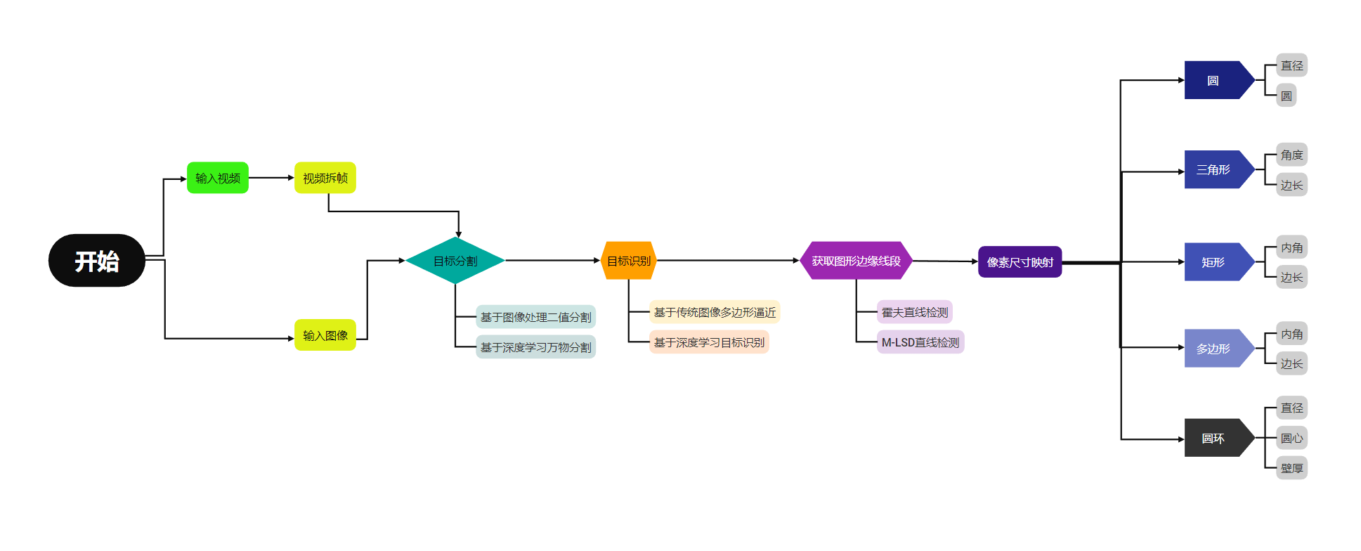 基于深度学习和传统图像处理方法之间区别: 基于深度学习和传统图像处理方法之间区别:
特征提取方法:
传统图像处理: 传统方法主要依赖于手工设计的特征提取器,如边缘检测器、滤波器等。这些方法通常需要对数字处理有专业知识才能选择和设计适当的特征提取方式。 深度学习: 深度学习模型能够自动地从数据中学习到最优的特征表示。卷积神经网络(CNN)等深度学习架构可以学习到图像中的抽象特征,无需手动设计特征提取器。
数据需求量:
传统图像处理: 传统方法对于特征的提取和处理通常需要有关专门领域的预定义知识,有时需要大量手动标注的数据。 深度学习: 深度学习方法对于大规模数据集的需求更为显著,尤其是需要大量标记的数据以训练复杂的深度神经网络。
通用性和灵活性:
传统图像处理: 传统方法通常针对特定问题设计,因此在其他问题上可能不具备通用性,场景泛化能力差。 深度学习: 深度学习模型可以更好地泛化到未见过的数据,并在不同领域中展现出更强的通用性和灵活性。
调参和复杂性:
传统图像处理: 传统方法通常需要手动调整参数和特征提取器的设计,这需要代码人员具有专业图像处理知识和经验。 深度学习: 深度学习模型通常有更多的超参数需要调整,并且相对更复杂。因此,训练深度学习模型可能需要更多的计算资源和时间。
适用范围:
传统图像处理: 传统方法在某些特定任务上仍然具有优势,例如简单的图像滤波、边缘检测等领域。 深度学习: 深度学习在许多领域取得了重大突破,例如图像分类、物体检测、分割、生成对抗网络等,使得在复杂问题上取得了更好的表现。
2.长度测量
图像里面的线段测量,首先要理解“每度量比的像素”(pixels per metric ratio),它类似于比例尺,通过已知图像上一个对象的尺寸和该对象在图像中所占像素的数量,可以得到一个比例关系,从而可以将其他物体的像素转换为实际度量单位(如厘米、毫米等)。
关键属性包括:
已知长度:需要知道图像中一个物体的实际长度,通常是以某种可测量的单位(例如毫米、英寸等)来表示。像素数量:该已知长度物体在图像中所占据的像素数。这可以通过在图像中测量该物体的像素宽度或高度来获取。
有了这两个属性,就可以计算出每个度量单位所对应的像素数。这个比例关系将图像中的像素转换为实际的度量单位,从而可以测量其他物体的大小或长度。 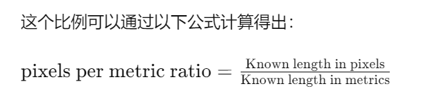 “Known length in pixels” 是图像中已知长度参考物体所占据的像素数,“Known length in metrics” 是已知长度参考物体的实际尺寸。 “Known length in pixels” 是图像中已知长度参考物体所占据的像素数,“Known length in metrics” 是已知长度参考物体的实际尺寸。
3、角度测量
在角度测量中,首先要明确一个定理,几何形状和其中的角度大小是与图像的比例无关的。在几何学中,角度的大小是由几何形状的内部构造和相对位置所确定的,而不受图像的放大或缩小影响。 当图像被放大或缩小时,图像中的对象尺寸和比例会改变,但这并不影响对象之间的相对位置和角度的大小。换句话说,图像的尺寸变化并不会改变对象内部的角度测量。 例如,如果一个图像中有一个特定角度的三角形,在放大或缩小图像的过程中,三角形内部的角度大小将保持不变。无论图像是多大还是多小,角度大小都取决于三角形的内部构造和边的相对位置,而不是取决于图像的尺寸或比例。由于角度在图像尺寸的变化过程中保持不变,图像中的角度测量就不用参照另外的参数。
三、代码实现
为了方便理解,这里实现所用的代码都是基于传统数字图像处理,实现依赖库是OpenCV,实现语言是Python,如果要应用到实际生产环境当中,这套方法并不是最可靠的,最好是选择使用流程图里面提到的基于深度学习的方法。
代码的实现是识别与测量放在一张A4纸上的所有几何图形的边长,内角值,直径,圆心。
1.数据处理
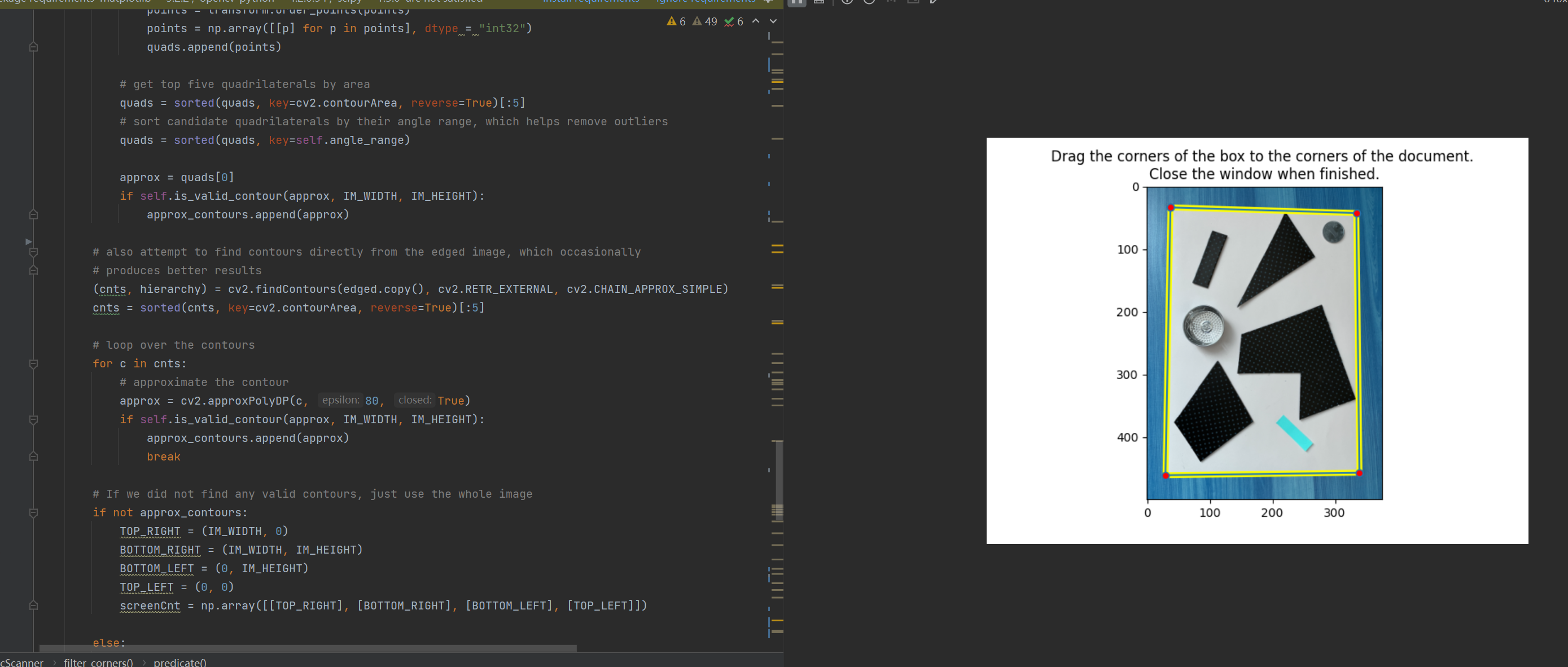
首先使用手机拍几张A4纸,纸上放着想要测量的几何图形目标,如下图:  使用代码把图像中的A4区域切出来: 使用代码把图像中的A4区域切出来:
from pyimagesearch import transform
from pyimagesearch import imutils
from matplotlib.patches import Polygon
import polygon_interacter as poly_i
import numpy as np
import matplotlib.pyplot as plt
import itertools
import math
import cv2
from pylsd.lsd import lsd
from scipy.spatial import distance as dist
def midpoint(ptA, ptB):
return ((ptA[0] + ptB[0]) * 0.5, (ptA[1] + ptB[1]) * 0.5)
class DocScanner(object):
"""An image scanner"""
def __init__(self, interactive=False, MIN_QUAD_AREA_RATIO=0.25, MAX_QUAD_ANGLE_RANGE=40):
self.interactive = interactive
self.MIN_QUAD_AREA_RATIO = MIN_QUAD_AREA_RATIO
self.MAX_QUAD_ANGLE_RANGE = MAX_QUAD_ANGLE_RANGE
def filter_corners(self, corners, min_dist=20):
"""Filters corners that are within min_dist of others"""
def predicate(representatives, corner):
return all(dist.euclidean(representative, corner) >= min_dist
for representative in representatives)
filtered_corners = []
for c in corners:
if predicate(filtered_corners, c):
filtered_corners.append(c)
return filtered_corners
def angle_between_vectors_degrees(self, u, v):
"""Returns the angle between two vectors in degrees"""
return np.degrees(
math.acos(np.dot(u, v) / (np.linalg.norm(u) * np.linalg.norm(v))))
def get_angle(self, p1, p2, p3):
a = np.radians(np.array(p1))
b = np.radians(np.array(p2))
c = np.radians(np.array(p3))
avec = a - b
cvec = c - b
return self.angle_between_vectors_degrees(avec, cvec)
def angle_range(self, quad):
tl, tr, br, bl = quad
ura = self.get_angle(tl[0], tr[0], br[0])
ula = self.get_angle(bl[0], tl[0], tr[0])
lra = self.get_angle(tr[0], br[0], bl[0])
lla = self.get_angle(br[0], bl[0], tl[0])
angles = [ura, ula, lra, lla]
return np.ptp(angles)
def get_corners(self, img):
lines = lsd(img)
corners = []
if lines is not None:
# separate out the horizontal and vertical lines, and draw them back onto separate canvases
lines = lines.squeeze().astype(np.int32).tolist()
horizontal_lines_canvas = np.zeros(img.shape, dtype=np.uint8)
vertical_lines_canvas = np.zeros(img.shape, dtype=np.uint8)
for line in lines:
x1, y1, x2, y2, _ = line
if abs(x2 - x1) > abs(y2 - y1):
(x1, y1), (x2, y2) = sorted(((x1, y1), (x2, y2)), key=lambda pt: pt[0])
cv2.line(horizontal_lines_canvas, (max(x1 - 5, 0), y1), (min(x2 + 5, img.shape[1] - 1), y2), 255, 2)
else:
(x1, y1), (x2, y2) = sorted(((x1, y1), (x2, y2)), key=lambda pt: pt[1])
cv2.line(vertical_lines_canvas, (x1, max(y1 - 5, 0)), (x2, min(y2 + 5, img.shape[0] - 1)), 255, 2)
lines = []
# find the horizontal lines (connected-components -> bounding boxes -> final lines)
(contours, hierarchy) = cv2.findContours(horizontal_lines_canvas, cv2.RETR_EXTERNAL, cv2.CHAIN_APPROX_NONE)
contours = sorted(contours, key=lambda c: cv2.arcLength(c, True), reverse=True)[:2]
horizontal_lines_canvas = np.zeros(img.shape, dtype=np.uint8)
for contour in contours:
contour = contour.reshape((contour.shape[0], contour.shape[2]))
min_x = np.amin(contour[:, 0], axis=0) + 2
max_x = np.amax(contour[:, 0], axis=0) - 2
left_y = int(np.average(contour[contour[:, 0] == min_x][:, 1]))
right_y = int(np.average(contour[contour[:, 0] == max_x][:, 1]))
lines.append((min_x, left_y, max_x, right_y))
cv2.line(horizontal_lines_canvas, (min_x, left_y), (max_x, right_y), 1, 1)
corners.append((min_x, left_y))
corners.append((max_x, right_y))
# find the vertical lines (connected-components -> bounding boxes -> final lines)
(contours, hierarchy) = cv2.findContours(vertical_lines_canvas, cv2.RETR_EXTERNAL, cv2.CHAIN_APPROX_NONE)
contours = sorted(contours, key=lambda c: cv2.arcLength(c, True), reverse=True)[:2]
vertical_lines_canvas = np.zeros(img.shape, dtype=np.uint8)
for contour in contours:
contour = contour.reshape((contour.shape[0], contour.shape[2]))
min_y = np.amin(contour[:, 1], axis=0) + 2
max_y = np.amax(contour[:, 1], axis=0) - 2
top_x = int(np.average(contour[contour[:, 1] == min_y][:, 0]))
bottom_x = int(np.average(contour[contour[:, 1] == max_y][:, 0]))
lines.append((top_x, min_y, bottom_x, max_y))
cv2.line(vertical_lines_canvas, (top_x, min_y), (bottom_x, max_y), 1, 1)
corners.append((top_x, min_y))
corners.append((bottom_x, max_y))
# find the corners
corners_y, corners_x = np.where(horizontal_lines_canvas + vertical_lines_canvas == 2)
corners += zip(corners_x, corners_y)
# remove corners in close proximity
corners = self.filter_corners(corners)
return corners
def is_valid_contour(self, cnt, IM_WIDTH, IM_HEIGHT):
"""Returns True if the contour satisfies all requirements set at instantitation"""
return (len(cnt) == 4 and cv2.contourArea(cnt) > IM_WIDTH * IM_HEIGHT * self.MIN_QUAD_AREA_RATIO
and self.angle_range(cnt) = 4:
quads = []
for quad in itertools.combinations(test_corners, 4):
points = np.array(quad)
points = transform.order_points(points)
points = np.array([[p] for p in points], dtype = "int32")
quads.append(points)
# get top five quadrilaterals by area
quads = sorted(quads, key=cv2.contourArea, reverse=True)[:5]
# sort candidate quadrilaterals by their angle range, which helps remove outliers
quads = sorted(quads, key=self.angle_range)
approx = quads[0]
if self.is_valid_contour(approx, IM_WIDTH, IM_HEIGHT):
approx_contours.append(approx)
# also attempt to find contours directly from the edged image, which occasionally
# produces better results
(cnts, hierarchy) = cv2.findContours(edged.copy(), cv2.RETR_EXTERNAL, cv2.CHAIN_APPROX_SIMPLE)
cnts = sorted(cnts, key=cv2.contourArea, reverse=True)[:5]
# loop over the contours
for c in cnts:
# approximate the contour
approx = cv2.approxPolyDP(c, 80, True)
if self.is_valid_contour(approx, IM_WIDTH, IM_HEIGHT):
approx_contours.append(approx)
break
# If we did not find any valid contours, just use the whole image
if not approx_contours:
TOP_RIGHT = (IM_WIDTH, 0)
BOTTOM_RIGHT = (IM_WIDTH, IM_HEIGHT)
BOTTOM_LEFT = (0, IM_HEIGHT)
TOP_LEFT = (0, 0)
screenCnt = np.array([[TOP_RIGHT], [BOTTOM_RIGHT], [BOTTOM_LEFT], [TOP_LEFT]])
else:
screenCnt = max(approx_contours, key=cv2.contourArea)
return screenCnt.reshape(4, 2)
def interactive_get_contour(self, screenCnt, rescaled_image):
poly = Polygon(screenCnt, animated=True, fill=False, color="yellow", linewidth=5)
fig, ax = plt.subplots()
ax.add_patch(poly)
ax.set_title(('Drag the corners of the box to the corners of the document. \n'
'Close the window when finished.'))
p = poly_i.PolygonInteractor(ax, poly)
plt.imshow(rescaled_image)
plt.show()
new_points = p.get_poly_points()[:4]
new_points = np.array([[p] for p in new_points], dtype = "int32")
return new_points.reshape(4, 2)
def scan(self, cv_src):
RESCALED_HEIGHT = 500.0
ratio = cv_src.shape[0] / RESCALED_HEIGHT
orig = cv_src.copy()
rescaled_image = imutils.resize(cv_src, height = int(RESCALED_HEIGHT))
# get the contour of the document
screenCnt = self.get_contour(rescaled_image)
if self.interactive:
screenCnt = self.interactive_get_contour(screenCnt, rescaled_image)
# apply the perspective transformation
warped = transform.four_point_transform(orig, screenCnt * ratio)
return warped
if __name__ == "__main__":
interactive_mode = 'store_true'
scanner = DocScanner(interactive_mode)
cv_src = cv2.imread('1.JPG')
cv_dst = scanner.scan(cv_src)
cv2.namedWindow('dst',0)
cv2.imshow('dst',cv_dst)
cv2.waitKey()
2.分割出图像里面的几何图形
cv_src = cv_or.copy()
dis_ref = dist.euclidean((start_point[0], start_point[1]), (end_point[0], end_point[1]))
blurred_image = cv2.GaussianBlur(cv_src, (11, 11), 0)
cv_gray = cv2.cvtColor(blurred_image, cv2.COLOR_BGR2GRAY)
_, threshold = cv2.threshold(cv_gray, 100, 255, cv2.THRESH_BINARY)
# threshold = cv2.adaptiveThreshold(cv_gray, 255, cv2.ADAPTIVE_THRESH_MEAN_C, cv2.THRESH_BINARY, 25,1)
# cv2.namedWindow('th',0)
# cv2.imshow('th',threshold)
# cv2.waitKey()
kernel = np.ones((13, 13), np.uint8)
# closed_image = cv2.morphologyEx(threshold, cv2.MORPH_CLOSE, kernel)
opened_image = cv2.morphologyEx(threshold, cv2.MORPH_OPEN, kernel)
erosion = cv2.erode(~opened_image, (3,3), iterations=1)
# cv2.imshow('op',erosion)

3.识别几何图形
import cv2
import numpy as np
# 读取图像并转换为灰度图
image = cv2.imread('shapes.jpg')
gray = cv2.cvtColor(image, cv2.COLOR_BGR2GRAY)
# 阈值化图像
_, thresh = cv2.threshold(gray, 240, 255, cv2.THRESH_BINARY)
# 查找轮廓
contours, _ = cv2.findContours(thresh, cv2.RETR_EXTERNAL, cv2.CHAIN_APPROX_SIMPLE)
for contour in contours:
# 计算轮廓的逼近多边形
approx = cv2.approxPolyDP(contour, 0.04 * cv2.arcLength(contour, True), True)
# 区分形状
if len(approx) == 3:
shape = "Triangle"
elif len(approx) == 4:
shape = "Rectangle"
else:
shape = "Circle"
# 在图像上绘制轮廓和形状名称
cv2.drawContours(image, [contour], -1, (0, 255, 0), 2)
cv2.putText(image, shape, (contour[0][0][0], contour[0][0][1]), cv2.FONT_HERSHEY_SIMPLEX,
0.5, (255, 255, 255), 2)
# 显示结果图像
cv2.imshow("Shapes", image)
cv2.waitKey(0)
cv2.destroyAllWindows()
4.线段长度测量
def measure_length(line,width,dis_ref):
distance = dist.euclidean((line[0][0],line[0][1]), (line[1][0],line[1][1]))
pixelsPerMetric = dis_ref / width
dim = distance / pixelsPerMetric
midpoint = ((line[0][0] + line[1][0]) // 2, (line[0][1] + line[1][1]) // 2)
return dim,midpoint
5.角度测量
#获取两条线的角度,返回角度值与交点
def measure_angle(line1,line2):
slope1 = (line1[1][1] - line1[0][1]) / (line1[1][0] - line1[0][0]) # 斜率1
slope2 = (line2[1][1] - line2[0][1]) / (line2[1][0] - line2[0][0]) # 斜率2
# 计算交点
x_intersect = (slope1 * line1[0][0] - slope2 * line2[0][0] + line2[0][1] - line1[0][1]) / (
slope1 - slope2)
y_intersect = slope1 * (x_intersect - line1[0][0]) + line1[0][1]
# 计算两条线之间的角度(弧度)
angle_rad = np.arctan(abs((slope2 - slope1) / (1 + slope1 * slope2)))
# 将弧度转换为角度
angle_deg = np.degrees(angle_rad)
angle = round(angle_deg, 1)
return angle,(int(x_intersect), int(y_intersect))
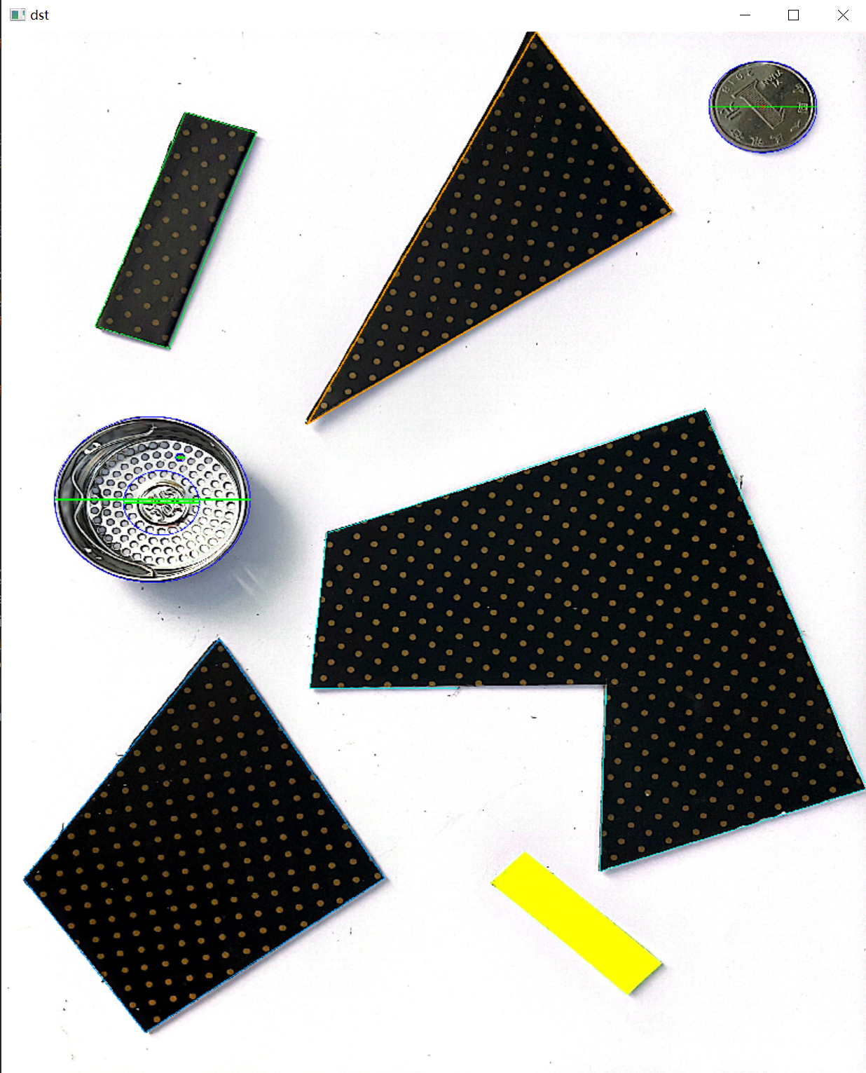
测试效果: 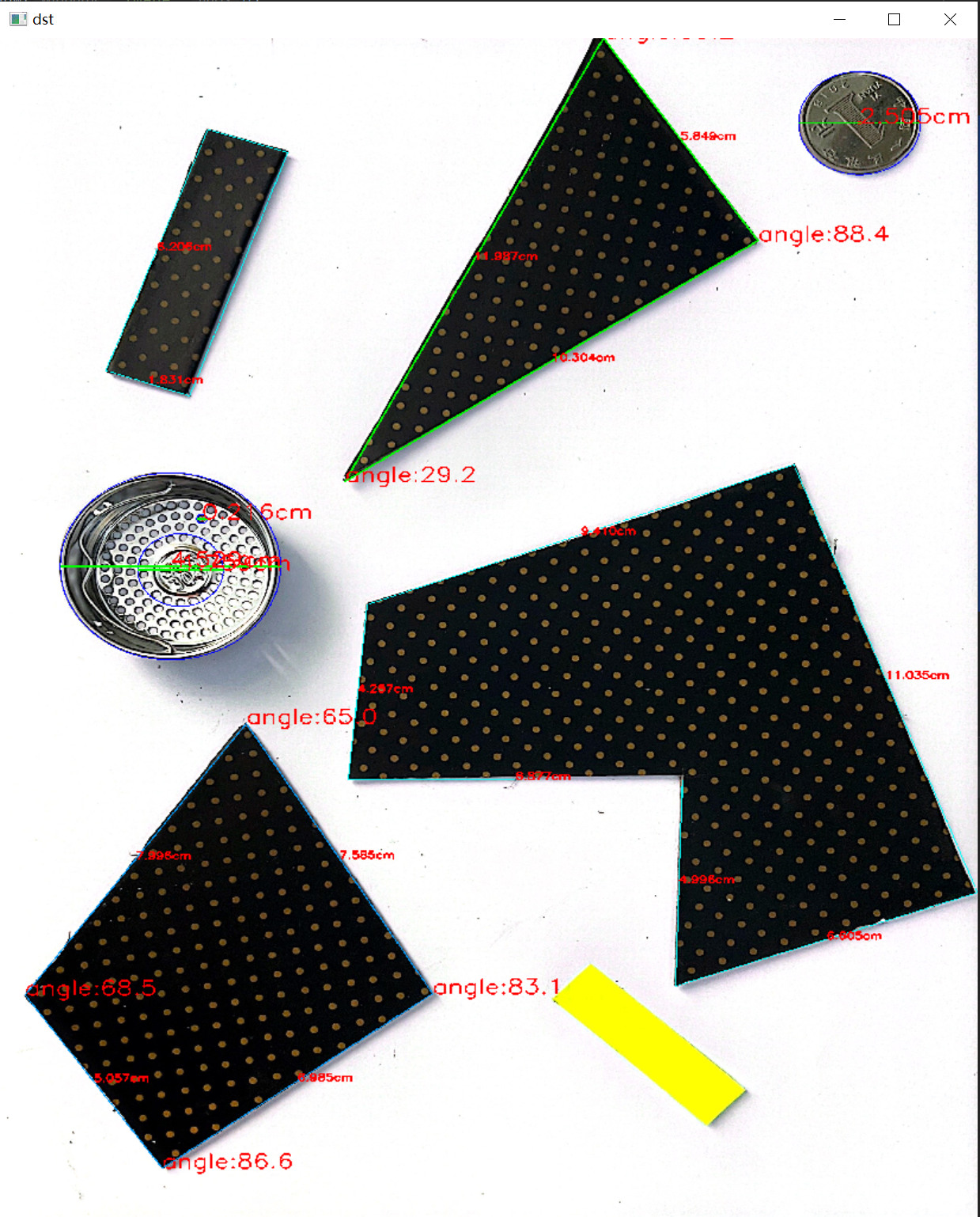 完整源码:https://download.csdn.net/download/matt45m/89053411?spm=1001.2014.3001.5503 完整源码:https://download.csdn.net/download/matt45m/89053411?spm=1001.2014.3001.5503
|