汽车转向系毕业设计(设计说明书+CAD+CAXA+译文) |
您所在的位置:网站首页 › 转向节尺寸设计图 › 汽车转向系毕业设计(设计说明书+CAD+CAXA+译文) |
汽车转向系毕业设计(设计说明书+CAD+CAXA+译文)
|
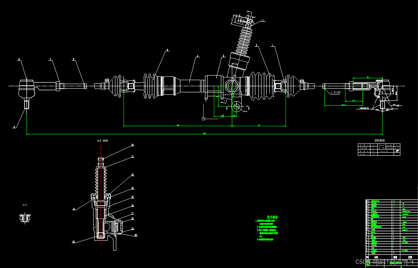
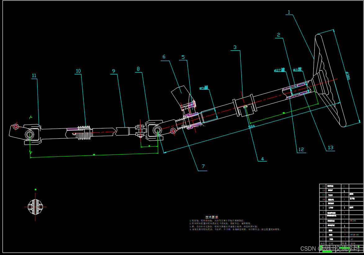
汽车转向系设计 [摘要] 本设计课题为汽车前轮转向系统的设计,课题以机械式转向系统的齿轮齿条式转向器设计及校核、转向操纵机构的设计,整体式转向梯形机构的设计为中心。首先对汽车转向系进行概述,二是作设计前期数据准备,三是转向器形式的选择以及初定各个参数,四是对齿轮齿条式转向器的主要部件进行受力分析与数据校核,在本设计中对转向器齿轮齿条的设计和对转向齿轮轴的校核,主要方法和理论采用汽车设计的经验参数和大学所学机械设计的课程内容进行设计,其结果满足强度要求,安全可靠。五是对整体式转向梯形机构的设计以及验算,并根据梯形数据对转向传动机构作尺寸设计。最后是作图部分,运用CAXA 作出转向系总装配图,齿轮齿条式转向器的零件图以及装配图,转向轴及万向节等零件图。 [关键词] 转向系统 齿轮齿条 梯形机构 Design of car steering system [Abstract] The title of this topic is the design of steering system. Rack and pinion steering of Mechanical steering system and integrated Steering trapezoid mechanism gear to the design as the center. Firstly make an overview of the Steering System. Secondly take a preparation of the data of the design. Thirdly, make a choice of the steering form and determine the primary parameters and design the structure of Rack and pinion steering. Fourthly, Stress analysis and data checking of the Rack and pinion steering. In this design to design of the steering rack and pinion steering gear shaft and the verification, the main method and theory with experience in automotive design parameters and the university curriculum design of mechanical design, and the results meet the strength requirments, safe and reliable. Fifthly, design of Steering trapezoid mechanism, according to the trapezoidal data make an analysis and design of Steering linkage,The use of caxa to make the steering system the general assembly,rack and pinion steering parts diagrams and assembly drawings ,steering shaft and universal joint graph. [Key words] Steering system Mechanical Type Steering Gear and GearRack tie rod linkage 目录 摘要........................................................................................................................................1 Abstract..................................................................................................................................2 1 绪论....................................................................................................................................5 1.1 汽车转向系统概述 ..............................................................................................5 1.2 汽车转向系统的国内外现状及发展趋势 ...........................................................6 1.3 研究内容及论文构成 .......................................................................................7 2 机械转向系统的性能要求及参数 ................................................................................8 2.1 机械转向系统的结构组成 ................................................................................8 2.2 转向系统的性能要求 .......................................................................................9 2.3 转向系的效率 ...................................................................................................10 2.4 传动比特性...........................................................................................................11 2.5 转向器传动副的传动间隙 ..............................................................................13 3 机械式转向器总体方案初步设计 ..............................................................................14 3.1 转向器的分类及设计选择 ..............................................................................15 3.2 齿轮齿条式转向器的基本设计 .......................................................................15 3.2.1 齿轮齿条式转向器的结构选择..............................................................15 3.2.2 齿轮齿条式转向器的布置形式..............................................................16 3.2.3 设计目标参数表以及对应的转向轮偏角计..........................................16 3.2.4 转向器参数选取与计算..........................................................................17 3.2.5 齿轮轴的结构设计..................................................................................18 3.2.6 转向器材料及其他零件选择..................................................................19 4 齿轮齿条转向器校核......................................................................................................21 4.1 齿条的强度计算...................................................................................................21 4.1.1 齿条受力分析..........................................................................................22 4.1.2 齿条齿根弯曲强度的计算......................................................................22 4.2 小齿轮的强度计算...............................................................................................22 4.2.1 齿面接触疲劳强度计算..........................................................................24 4.2.2 齿轮齿根弯曲疲劳强度计算..................................................................25 4. 3 齿轮轴强度校核..................................................................................................26 5 转向梯形机构的设计......................................................................................................29 5.1 转向梯形机构概述...............................................................................................29 5.2 断开式转向梯形机构方案分析...........................................................................29 5.3 断开式转向梯形机分析......................................................................................29 6转向传动机构和操纵机构设计......................................................................................35 6.1 转向传送机构的臂、杆与球销..........................................................................35 6.2 转向横拉杆及其端部..........................................................................................35 6.3 转向盘的尺寸和布置..........................................................................................36 6.4转向轴的防伤安全措施.......................................................................................37 7 基于CAXA的齿轮齿条式转向系统的二维绘图........................................................38 7.1 CAXA软件简介................................................................................................38 7.2 齿轮齿条式转向系统的主要部件二维绘图......................................................38 结论.....................................................................................................................................39 致 谢.................................................................................................................................40 参考文献.............................................................................................................................41
|
【本文地址】


