|
第一篇:最简单DIY基于ESP32CAM的物联网相机系统①(用网页实现拍照图传) 第二篇:最简单DIY基于ESP32CAM的物联网相机系统②(在JAVAWEB服务器实现图片查看器) 第三篇:最简单DIY基于ESP32CAM的物联网相机系统③(在JSP服务器图传相片给所有客户端欣赏) 第四篇:最简单DIY基于ESP32CAM的物联网相机系统④(用调试串口助手实现串口图传) 第五篇(上):最简单DIY基于ESP32CAM的物联网相机系统⑤(用1306OLED实现WIFI黑白屏照相机)
文章目录
前言一、最简单DIY基于ESP32CAM的物联网相机系统⑤(用1306OLED实现WIFI黑白屏照相机)是什么?二、实现需求1.先打开官方1306显示屏的代码2.再打开官方ESP32CAM照相机程序3.修改上面1和2的官方源码变成自己的源码
三、运行与调试总结
前言
daodanjishui物联网核心原创技术之最简单DIY基于ESP32CAM的物联网相机系统⑤(用1306OLED实现WIFI黑白屏照相机)。 该专栏的第四篇博文:最简单DIY基于ESP32CAM的物联网相机系统④(用调试串口助手实现串口图传) 实现的是用ESP32CAM拍摄照片传输到电脑串口调试助手,在串口调试助手里面拷贝图片信息出来放到图片查看器可以看到拍摄的图片,其实这样很麻烦。 在这篇博文,我将会带大家用最便宜的0.96寸1306OLED黑白显示屏显示ESP32CAM单片机拍摄的图片,就像真正的相机一样拍完照片之后可以直接在相机的屏幕上查看拍摄照片的效果。显示屏是直接通过I2C总线连接在ESP32CAM单片机上的。 优酷视频演示地址:https://v.youku.com/v_show/id_XNTE1Mzk2MTUwOA==.html
最简单DIY基于ESP32CAM的物联网相机系统⑤(用1306OLED实现WIFI黑白屏照相机)
显示屏外形: 
该设计的全家福如下所示:  另外我还加入了STA模式,相机可以连接路由器,在局域网的所有用户都可以根据OLED显示的局域网IP=192.168.252.10,访问相机的嵌入式主页,如下图所示,控制拍照的依旧是网页: 另外我还加入了STA模式,相机可以连接路由器,在局域网的所有用户都可以根据OLED显示的局域网IP=192.168.252.10,访问相机的嵌入式主页,如下图所示,控制拍照的依旧是网页: 
一、最简单DIY基于ESP32CAM的物联网相机系统⑤(用1306OLED实现WIFI黑白屏照相机)是什么?
用0.96寸的OLED显示屏来显示ESP32CAM相机拍摄的黑白照片。
二、实现需求
1.先打开官方1306显示屏的代码
在Arduino IDE有很多例子供开发者学习的。 (1)第一个相关的例子就是串口通信的例子了: 源码路径: 
/**************************************************************************
This is an example for our Monochrome OLEDs based on SSD1306 drivers
Pick one up today in the adafruit shop!
------> http://www.adafruit.com/category/63_98
This example is for a 128x64 pixel display using I2C to communicate
3 pins are required to interface (two I2C and one reset).
Adafruit invests time and resources providing this open
source code, please support Adafruit and open-source
hardware by purchasing products from Adafruit!
Written by Limor Fried/Ladyada for Adafruit Industries,
with contributions from the open source community.
BSD license, check license.txt for more information
All text above, and the splash screen below must be
included in any redistribution.
**************************************************************************/
#include
#include
#include
#include
#define SCREEN_WIDTH 128 // OLED display width, in pixels
#define SCREEN_HEIGHT 64 // OLED display height, in pixels
// Declaration for an SSD1306 display connected to I2C (SDA, SCL pins)
#define OLED_RESET 4 // Reset pin # (or -1 if sharing Arduino reset pin)
Adafruit_SSD1306 display(SCREEN_WIDTH, SCREEN_HEIGHT, &Wire, OLED_RESET);
#define NUMFLAKES 10 // Number of snowflakes in the animation example
#define LOGO_HEIGHT 16
#define LOGO_WIDTH 16
static const unsigned char PROGMEM logo_bmp[] =
{ B00000000, B11000000,
B00000001, B11000000,
B00000001, B11000000,
B00000011, B11100000,
B11110011, B11100000,
B11111110, B11111000,
B01111110, B11111111,
B00110011, B10011111,
B00011111, B11111100,
B00001101, B01110000,
B00011011, B10100000,
B00111111, B11100000,
B00111111, B11110000,
B01111100, B11110000,
B01110000, B01110000,
B00000000, B00110000 };
void setup() {
Serial.begin(9600);
// SSD1306_SWITCHCAPVCC = generate display voltage from 3.3V internally
if(!display.begin(SSD1306_SWITCHCAPVCC, 0x3D)) { // Address 0x3D for 128x64
Serial.println(F("SSD1306 allocation failed"));
for(;;); // Don't proceed, loop forever
}
// Show initial display buffer contents on the screen --
// the library initializes this with an Adafruit splash screen.
display.display();
delay(2000); // Pause for 2 seconds
// Clear the buffer
display.clearDisplay();
// Draw a single pixel in white
display.drawPixel(10, 10, SSD1306_WHITE);
// Show the display buffer on the screen. You MUST call display() after
// drawing commands to make them visible on screen!
display.display();
delay(2000);
// display.display() is NOT necessary after every single drawing command,
// unless that's what you want...rather, you can batch up a bunch of
// drawing operations and then update the screen all at once by calling
// display.display(). These examples demonstrate both approaches...
testdrawline(); // Draw many lines
testdrawrect(); // Draw rectangles (outlines)
testfillrect(); // Draw rectangles (filled)
testdrawcircle(); // Draw circles (outlines)
testfillcircle(); // Draw circles (filled)
testdrawroundrect(); // Draw rounded rectangles (outlines)
testfillroundrect(); // Draw rounded rectangles (filled)
testdrawtriangle(); // Draw triangles (outlines)
testfilltriangle(); // Draw triangles (filled)
testdrawchar(); // Draw characters of the default font
testdrawstyles(); // Draw 'stylized' characters
testscrolltext(); // Draw scrolling text
testdrawbitmap(); // Draw a small bitmap image
// Invert and restore display, pausing in-between
display.invertDisplay(true);
delay(1000);
display.invertDisplay(false);
delay(1000);
testanimate(logo_bmp, LOGO_WIDTH, LOGO_HEIGHT); // Animate bitmaps
}
void loop() {
}
void testdrawline() {
int16_t i;
display.clearDisplay(); // Clear display buffer
for(i=0; i=0; i-=4) {
display.drawLine(display.width()-1, display.height()-1, 0, i, SSD1306_WHITE);
display.display();
delay(1);
}
delay(250);
display.clearDisplay();
for(i=0; ibuf[i] = newpixel; //缓冲区现在是单通道,0或255
// floyd-steignburg抖动算法
quanterror = oldpixel - newpixel; //像素之间的误差
//将此错误分发给相邻像素:
//右
if(x buf[(x + 1)+(y * SCREEN_WIDTH)] += ((quanterror * 7)>> 4);
}
// 左下
if((x > 1) && (y buf [(x-1)+((y + 1)* SCREEN_WIDTH)] == ((quanterror * 3)>> 4);
}
//下
if(y buf [(x)+((y + 1)* SCREEN_WIDTH)] == ((quanterror * 5)>> 4);
}
// 右下
if((x > 4);
}
// 画这个像素
switch(fb->buf[i]%2)
{
case 0:
//display.setColor(BLACK);
display.drawPixel(x,y,BLACK);
break;
case 1:
//display.setColor(WHITE);
// draw a single pixel
display.drawPixel(x,y,WHITE);
break;
case 2:
//display.setColor(INVERSE);
// draw a single pixel
display.drawPixel(x,y,INVERSE);
break;
}
//display.setPixel(x, y);
i++;
}
}
display.display();
esp_camera_fb_return(fb);
}
(2)结合图像采集和图像处理完成最终的OLED显示的设计 需要完整代码的读者请到最后面的链接下载工程源码。这里省去几千字的代码······
三、运行与调试
(1)按照下图接线: 
(1.1)配置好路由器的账号和密码烧录代码开机,查看OLED显示屏的IP地址: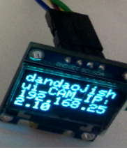
(2)打开浏览器输入IP地址进入智能照相机主页(相机和浏览器都要在一个局域网): 
(3)点击send之后就会触发ESP32CAM在拍照,OLED 马上显示拍摄的黑白照片。 
调试到此结束,根据结果可以满足博文提出的要求。
总结
总结:读者可以在这里学会了AJAX技术,可以在不刷新网页的前提下不断点击send按钮拍照,并且网页会显示一个变化的随机数nocathe=1620924773578 提示用户拍照成功,这个反馈不知道有多少个技术开发者想写都难写出来的,因为这个技术要熟悉JS技术才能使用得淋漓尽致了,还有就是可以学到嵌入式网页设计及嵌入式服务器的设计及嵌入式服务器如何接受get请求和用异步响应get请求,服务器根据请求验证提交表单的账号和密码,并没有使用到数据库又可以实现账号密码认证,多少硬件工程师都想不出来是这样写的,根据密码认证的结果解析指令控制照相机硬件摄像头拍照,总的来说不简单的,网上开源的老外代码没有我的那么详细和简洁的,相信daodanjishui品牌的力量,后期我可能会去编写一本关于ESP32CAM的技术书籍,玩技术又有冒险的尝试和收割成果的喜悦,大概就是所谓的技术真爱吧!这是我以前的项目中没有出现过的知识点(后期还会开源在ESP32CAM本机加载JS库的开源代码实现图像处理,敬请期待······)包括串口图传,WIFI图传,C#图传,JAVA图传,安卓图传,JSP图传,MFC图传······精彩值得期待。
代码工程下载链接:https://gf.bilibili.com/item/detail/1107789114 点我直接跳转
|