激光雷达与相机时间同步问题的低成本完整解决方案 |
您所在的位置:网站首页 › 激光雷达视频 › 激光雷达与相机时间同步问题的低成本完整解决方案 |
激光雷达与相机时间同步问题的低成本完整解决方案
|
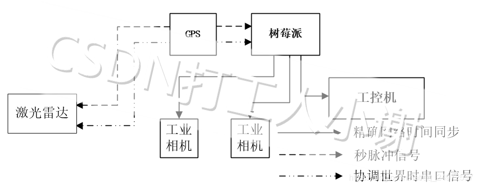
给博主的另一篇文章打个广告: Pytorch在finetune和multi-task任务的一个小坑(与BN层推理相关的坑) 激光雷达和相机的时间同步是做自动驾驶感知方面实验的基础,目前网络上给出的各种解决方案都不是很完整,博主也走了不少弯路,最后探索出一个较为完整的低成本解决方案(重点是低成本,可靠性一般)。这是第一次在CSDN上写作,写得不好或者有遗漏之处还请各位看官在评论区指出,我会尽快回复。 文章目录 总体技术路线设备选型激光雷达和相机的内部时钟同步GPS到激光雷达的时间同步GPS到树莓派的时间同步/树莓派做PTP授时服务器树莓派串口配置开启树莓派pps-gpio关闭树莓派ntpd功能使用gpsd和chronyd对树莓派进行授时,使用ptp4l把树莓派配置为授时服务器gpsd配置chronyd配置PTP4l配置 树莓派到工控机的时间同步更改ptp4l配置文件更改chronyd配置文件 树莓派到相机的时间同步 激光雷达和相机的同步采集更进一步参考文献本博文原创,转发请注明出处! 总体技术路线激光雷达和相机的时间同步是多传感器融合是先决条件,但是精确的时间同步需要涉及到软件和硬件的相关知识,因此也是不大容易实现的。下面是目前网络上已有的资料(截止到2021.03.21): 激光雷达与相机标定时的时间同步问题怎么进行解决?在自动驾驶领域,如何实现激光雷达和相机的时间同步呢?激光雷达与相机标定的时间戳同步问题Camera-LIDAR_Detection_Fusion无人驾驶中和传感器有关的事儿其中苏笑云大佬的回答是比较清晰。大佬提到:更彻底的解决方法是选择可以触发拍摄的相机(必须是硬件线控),根据激光雷达的帧周期同步触发相机的拍摄,实现雷达和相机的完全帧同步,实现完全的毫秒级同步。 本文也是根据这个解决方案来做的。所谓激光雷达与相机时间同步其实涉及到两个问题:一个是激光雷达和相机的内部时钟要同步;一个是激光雷达和相机要同时采集数据。因此本文也是从这两个方面来进行技术路线的描述的。本文的技术路线也参考了上述的论文《Camera-LIDAR_Detection_Fusion》,有一说一,这篇本科毕业论文写得很不错! 设备选型 GPS,能够输出PPS和NMEA串口信号,淘宝有很多款可以支持,不过买回来需要用示波器测试一下,博主就踩过劣质GPS的坑…树莓派,作为网络授时主时钟,应该随便一款应该都行,博主使用的是树莓派4B+相机,要能够支持外部硬件触发,要能支持PTP时间同步功能,要能支持输出图像曝光时相机的内部时间戳,博主使用的是Basler的工业相机激光雷达,要能支持基于PPS和NMEA的时间同步(或者PTP时间同步,虽然博主没有调通这个功能),能够支持输出点云采集时激光雷达内部的时间戳,博主使用的是速腾激光雷达单片机,把GPS输出的PPS信号转发为同相位的10Hz方波,给相机做硬件触发,要求单片机支持定时器,中断,GPIO,博主还没来得及实现单片机的功能,目测STM32就可以了。 激光雷达和相机的内部时钟同步
这个需要参考的激光雷达说明文档啦,像速腾激光雷达,还对PPS和NMEA串口信号的格式做个限制,所以需要提前用示波器看买来的GPS模块是否符合要求。这一步成功之后,在RSVIEW的web端的GPS Data一栏会显示串口信息、GPS Status和PPS Status一栏Locked。 GPS到树莓派的时间同步/树莓派做PTP授时服务器这一步比较麻烦。这里主要使用的是gpsd、chronyd、ptp4l这几个软件。博主假设树莓派已经刷了官方系统,接好了各种外设。 树莓派串口配置由于树莓派外设一共包含两个串口,一个称之为硬件串口(/dev/ttyAMA0),一个称之为mini串口(/dev/ttyS0)。硬件串口由硬件实现,有单独的波特率时钟源,性能高、可靠。树莓派(3/4代)板载蓝牙模块,默认的硬件串口是分配给蓝牙模块使用的,而性能较差的mini串口是分配给GPIO串口 TXD0、RXD0。但是我们不能使用mini串口,因此得把硬件串口分配给GPIO串口 TXD0、RXD0。具体的方法在网上可以查到很多资源,这里推荐树莓派的官方教程。这一步做完后,接好线,然后使用串口工具cutecom就可以查到GPS发过来的串口信号了。也可以使用gpsmon对GPS信号进行解析。 开启树莓派pps-gpio为什么精确授时需要pps和NMEA缺一不可呢?这是因此设备处理NMEA信息(通常是串口信号)需要较长时间,处理完就已经早就错过NMEA信息所描述的那个时刻了。而PPS是一个1hz的方波,方波的上升沿可以触发设备的硬件中断功能,同时记录下这个时刻,这样处理完NMEA信息的时候,就知道对应的是哪个时刻了。开启树莓派pps-gpio功能的教程是这个。配置完成后,重启树莓派,使用ppstest去测试。 关闭树莓派ntpd功能因为我们需要让树莓派跟gps同步,因此需要关闭树莓派ntpd功能,避免树莓派通过网络时间同步。在命令行输入rcconf,安装提示操作就可以了,很简单。 使用gpsd和chronyd对树莓派进行授时,使用ptp4l把树莓派配置为授时服务器终于到重点了,这里先对这三个软件的功能做一个介绍。 gpsd的功能是解析NMEA信息和pps信号,获取当前GPS时间,但是它没有办法给树莓派系统授时;chronyd能够给树莓派系统授时,但是需要从gpsd获取当前GPS时间,chronyd和gpsd的通讯是通过共享内存实现的,这需要对chronyd做一定的配置;ptp4l是PTP同步,即精确网络时间同步协议的软件,它需要从chronyd获取系统当前时间,然后发布到局域网,给相机和工控机授时,ptp4l与chronyd的通讯也是通过共享内存。下面分别介绍怎么配置这三个软件: gpsd配置其实并不需要配置,直接开启就完事了哈哈。 sudo killall -9 gpsd chronyd sudo gpsd -n -G /dev/ttyAMA0但是开启之后,需要用一些软件来测试一下有没有开启成功。如下面所示: gpsmon ---------------------------------------------------------- /dev/ttyAMA0 u-blox> ┌──────────────────────────┐┌─────────────────────────────────────────────────┐ or":12} │Ch PRN Az El S/N Flag U ││ECEF Pos: -2324739.37m +5387509.44m +2492042.31m │ ver":"u-blox","subtype":"SW ROM CORE 3.01 (107888),HW 00080000,FWVER=SPG 3.01,PROTVER=18","activated":"20 │ 0 3 224 6 28 060f Y ││ECEF Vel: +0.02m/s +0.03m/s +0.01m/s │ 1,"cycle":1.00,"mincycle":0.25}]} │ 1 4 262 62 26 060f Y ││ │ false,"timing":false,"split24":false,"pps":true} │ 2 7 313 8 30 070f Y ││LTP Pos: 23.150042180° 113.340458154° 96.91m │ │ 3 8 208 56 28 060f Y ││LTP Vel: 0.03m/s 272.8° 0.02m/s │ │ 4 9 303 36 28 070f Y ││ │ │ 5 11 0 165 29 0710 ││Time: 51 15:33:40.00 │ │ 6 16 21 43 28 070f Y ││Time GPS: 2150+446242.000 Day: 5 │ │ 7 18 51 3 25 040c ││ │ │ 8 21 179 8 0 010c ││Est Pos Err 11.51m Est Vel Err 0.00m/s │ │ 9 22 201 3 0 010c ││PRNs: 6 PDOP: 2.6 Fix 0x03 Flags 0xdf │ │10 26 48 26 0 010c │└─────────────────── NAV_SOL ─────────────────────┘ │11 27 75 81 35 070f Y │┌─────────────────────────────────────────────────┐ │12 31 109 21 43 070c ││DOP [H] 1.8 [V] 2.0 [P] 2.6 [T] 1.6 [G] 3.1 │ │13 127 256 21 0 0004 │└─────────────────── NAV_DOP ─────────────────────┘ │14 128 236 47 39 070c │┌─────────────────────────────────────────────────┐ │15 132 223 55 0 0104 ││TOFF: 0.095508862 PPS: -0.000000278 │ └────── NAV_SVINFO ────────┘└─────────────────────────────────────────────────┘ ------------------- PPS offset: 0.000000096 ------ (60) b56201063400300d991aa5640300660803df98ba24f2c8af1c20278eda0e740400000200000003000000030000002200000009010306e04a0300214c (26) b56201041200300d991a36010901a000c500b2004c00a1004ca3 (24) b56201201000300d991aa56403006608120745000000f938 ------------------- PPS offset: 0.000000368 ------ sudo ntpshmon ---------------------------------------------------------- pi@raspberrypi:~ $ sudo ntpshmmon ntpshmmon version 1 # Name Seen@ Clock Real L Prec sample NTP0 1616731155.261334631 1616731155.090788722 1616731155.000000000 0 -20 sample NTP1 1616731155.261480981 1616731154.999999776 1616731155.000000000 0 -30 sample NTP1 1616731156.001005646 1616731155.999999600 1616731156.000000000 0 -30 sample NTP0 1616731156.091572631 1616731156.090540716 1616731156.000000000 0 -20 sample NTP1 1616731157.000122016 1616731156.999999202 1616731157.000000000 0 -30 sample NTP0 1616731157.090672594 1616731157.090357912 1616731157.000000000 0 -20 sample NTP1 1616731158.000105988 1616731157.999998915 1616731158.000000000 0 -30 sample NTP0 1616731158.090650363 1616731158.090550734 1616731158.000000000 0 -20 sample NTP1 1616731159.000270238 1616731158.999998408 1616731159.000000000 0 -30 sample NTP0 1616731159.091943158 1616731159.090915761 1616731159.000000000 0 -20 chronyd配置chronyd有一个默认配置文件,修改配置文件即可。下面是整个配置文件,复制黏贴保存为conf即可。其中最后三行代码是重点,配置了跟gpsd和ptp4l的共享内存参数。 # Welcome to the chrony configuration file. See chrony.conf(5) for more # information about usuable directives. pool 2.debian.pool.ntp.org iburst # This directive specify the location of the file containing ID/key pairs for # NTP authentication. keyfile /etc/chrony/chrony.keys # This directive specify the file into which chronyd will store the rate # information. driftfile /var/lib/chrony/chrony.drift # Uncomment the following line to turn logging on. #log tracking measurements statistics # Log files location. logdir /var/log/chrony # Stop bad estimates upsetting machine clock. maxupdateskew 100.0 # This directive enables kernel synchronisation (every 11 minutes) of the # real-time clock. Note that it can’t be used along with the 'rtcfile' directive. rtcsync # Step the system clock instead of slewing it if the adjustment is larger than # one second, but only in the first three clock updates. makestep 1 3 server 0.cn.pool.ntp.org server 1.cn.pool.ntp.org server 2.cn.pool.ntp.org server 3.cn.pool.ntp.org driftfile /var/lib/chrony/drift allow refclock SHM 0 refid GPS precision 1e-1 offset 0.9999 delay 0.2 refclock SHM 1 refid PPS precision 1e-7 refclock SHM 2 refid PTP precision 1e-7配置文件保存后,开启chronyd。 sudo chronyd -f /path/to/mychrony.conf chronyc sources -v等待半分钟,应该会显示系统已经与pps同步,如下: pi@raspberrypi:~ $ chronyc sources -v 210 Number of sources = 11 .-- Source mode '^' = server, '=' = peer, '#' = local clock. / .- Source state '*' = current synced, '+' = combined , '-' = not combined, | / '?' = unreachable, 'x' = time may be in error, '~' = time too variable. || .- xxxx [ yyyy ] +/- zzzz || Reachability register (octal) -. | xxxx = adjusted offset, || Log2(Polling interval) --. | | yyyy = measured offset, || \ | | zzzz = estimated error. || | | \ MS Name/IP address Stratum Poll Reach LastRx Last sample =============================================================================== #x GPS 0 4 377 18 -909ms[ -909ms] +/- 200ms #* PPS 0 4 377 18 -470ns[ -580ns] +/- 1129ns #? PTP 0 4 0 - +0ns[ +0ns] +/- 0ns ^- 203.107.6.88 2 7 377 89 -1073us[-1074us] +/- 36ms ^- ntp1.ams1.nl.leaseweb.net 3 6 377 17 -21ms[ -21ms] +/- 252ms ^? time.cloudflare.com 0 6 0 - +0ns[ +0ns] +/- 0ns ^- 119.28.206.193 2 7 277 82 +13ms[ +13ms] +/- 42ms ^- ntp6.flashdance.cx 2 7 363 21 -10ms[ -10ms] +/- 205ms ^- 139.199.215.251 2 7 277 94 -2922us[-2923us] +/- 46ms ^- 139.199.214.202 2 7 375 221 -2571us[-2571us] +/- 26ms ^- ntp7.flashdance.cx 2 7 377 85 -22ms[ -22ms] +/- 215msKnown Issue:有时候树莓派需要联网才能跟pps同步。。。有哪位大佬知道为啥的麻烦指导一波 PTP4l配置配置文件如下。其中重点是这几个参数priority1、logAnnounceInterval、logSyncInterval、time stamping、ntpshm_segment。前四者是为了保证相机能够通过PTP与树莓派时间同步(具体解释见《Camera-LIDAR_Detection_Fusion》这篇本科毕业论文,或者见Basler官方文档),最后一个是为了是ptp4l能跟chronyd通讯。 [global] # # Default Data Set # twoStepFlag 1 slaveOnly 0 # priority1 128 priority1 127 priority2 128 domainNumber 0 #utc_offset 37 clockClass 248 clockAccuracy 0xFE offsetScaledLogVariance 0xFFFF free_running 0 freq_est_interval 1 dscp_event 0 dscp_general 0 # # Port Data Set # logAnnounceInterval 1 # logSyncInterval 0 logSyncInterval -1 logMinDelayReqInterval 0 logMinPdelayReqInterval 0 announceReceiptTimeout 3 syncReceiptTimeout 0 delayAsymmetry 0 fault_reset_interval 4 neighborPropDelayThresh 20000000 # # Run time options # assume_two_step 0 logging_level 6 path_trace_enabled 0 follow_up_info 0 hybrid_e2e 0 net_sync_monitor 0 tx_timestamp_timeout 1 use_syslog 1 # verbose 0 verbose 1 summary_interval 0 kernel_leap 1 check_fup_sync 0 # # Servo Options # pi_proportional_const 0.0 pi_integral_const 0.0 pi_proportional_scale 0.0 pi_proportional_exponent -0.3 pi_proportional_norm_max 0.7 pi_integral_scale 0.0 pi_integral_exponent 0.4 pi_integral_norm_max 0.3 step_threshold 0.0 first_step_threshold 0.00002 max_frequency 900000000 # clock_servo pi clock_servo ntpshm sanity_freq_limit 200000000 # ntpshm_segment 0 ntpshm_segment 2 # # Transport options # transportSpecific 0x0 ptp_dst_mac 01:1B:19:00:00:00 p2p_dst_mac 01:80:C2:00:00:0E udp_ttl 1 udp6_scope 0x0E uds_address /var/run/ptp4l # # Default interface options # network_transport UDPv4 delay_mechanism E2E # time_stamping hardware time_stamping software tsproc_mode filter delay_filter moving_median delay_filter_length 10 egressLatency 0 ingressLatency 0 boundary_clock_jbod 0 # # Clock description # productDescription ;; revisionData ;; manufacturerIdentity 00:00:00 userDescription ; timeSource 0xA0配置文件保存后,开启ptp4l。 /usr/sbin/ethtool --set-eee eth0 eee off /usr/sbin/ifconfig eth0 192.168.2.158 nohup /usr/sbin/ptp4l -f /path/to/myptp4l.conf -i eth0 & 树莓派到工控机的时间同步由于树莓派已经配置为PTP授时服务器(master),那么工控机只要配置成PTP授时客户端(slave)即可。工控机使用的是ptp4l和chronyd两个软件,ptp4l与树莓派通讯获取当前时间,并通过共享内存的方式传递给chronyd,而chronyd更改系统时间,使系统时间与树莓派同步。 更改ptp4l配置文件首先ptp4l的配置文件需要做一点儿修改,主要是ntpshm_segment要改为0,全部配置文件如下: [global] # # Default Data Set # twoStepFlag 1 # slaveOnly 0 slaveOnly 1 priority1 128 priority2 128 domainNumber 0 clockClass 248 clockAccuracy 0xFE offsetScaledLogVariance 0xFFFF free_running 0 freq_est_interval 1 dscp_event 0 dscp_general 0 # # Port Data Set # logAnnounceInterval 1 logSyncInterval 0 logMinDelayReqInterval 0 logMinPdelayReqInterval 0 announceReceiptTimeout 3 syncReceiptTimeout 0 delayAsymmetry 0 fault_reset_interval 4 neighborPropDelayThresh 20000000 # # Run time options # assume_two_step 0 logging_level 6 path_trace_enabled 0 follow_up_info 0 hybrid_e2e 0 tx_timestamp_timeout 1 use_syslog 1 verbose 0 summary_interval 0 kernel_leap 1 check_fup_sync 0 # # Servo Options # pi_proportional_const 0.0 pi_integral_const 0.0 pi_proportional_scale 0.0 pi_proportional_exponent -0.3 pi_proportional_norm_max 0.7 pi_integral_scale 0.0 pi_integral_exponent 0.4 pi_integral_norm_max 0.3 step_threshold 0.0 first_step_threshold 0.00002 max_frequency 900000000 # clock_servo pi clock_servo ntpshm sanity_freq_limit 200000000 ntpshm_segment 0 # # Transport options # transportSpecific 0x0 ptp_dst_mac 01:1B:19:00:00:00 p2p_dst_mac 01:80:C2:00:00:0E udp_ttl 1 udp6_scope 0x0E uds_address /var/run/ptp4l # # Default interface options # network_transport UDPv4 delay_mechanism E2E # time_stamping hardware time_stamping software tsproc_mode filter delay_filter moving_median delay_filter_length 10 egressLatency 0 ingressLatency 0 boundary_clock_jbod 0 # # Clock description # productDescription ;; revisionData ;; manufacturerIdentity 00:00:00 userDescription ; timeSource 0xA0配置文件保存后,开启ptp4l sudo killall -9 ptp4l chronyd nohup sudo ptp4l -f /path/to/myptp4l.conf -i enp3s0 & 更改chronyd配置文件chronyd的配置文件更改如下。主要还是refclock SHM的配置。至于为啥工控机和树莓派的chronyd配置文件长得很不一样,猜测应该是不同架构的软件包配置文件有所差异吧。 #refclock SHM 0 delay 0.5 refid NEMA refclock SHM 0 refid PTP precision 1e-7 refclock SHM 1 offset 0 delay 0.001 refid PPS #refclock SOCK /var/run/chrony.ttyS1.sock delay 0.0 refid SOCK # C(20180207) Setings for using USB non-PPS GPS device and GPSD # NEMA is too inaccurate and chrony will not use anyway! # Need to fiddle with offset (seconds) to make sure refclock is considered # watch the output of 'chronyc sources' to see 'Last Sample' # # refclock SHM 0 offset 0.05 refid NMEA server clock.fmt.he.net iburst server clock.sjc.he.net iburst server time.cloudflare.com iburst server time.google.com iburst server time.nist.gov server gpstime.la-archdiocese.net #server time1.google.com iburst #server time2.google.com iburst #server time3.google.com iburst #server time4.google.com iburst #pool 0.ubuntu.pool.ntp.org iburst #pool 2.debian.pool.ntp.org offline iburst # Specify IP address (interface) that chronyd CLIENT will bind to # The bindacqaddress directive sets the network interface to which # chronyd will bind its NTP client sockets # bindacqaddress 0.0.0.0 # Allow other NTP clients in our zone to query time allow 10.3/16 allow 10.30.0/24 # (CHANGED): chronyd version 3.2 commandkey directive is no longer supported # This directive sets the key ID used for authenticating user commands via the # 'chronyc' program at run time. # commandkey 1 # End of customized settings - EXCEPT lines labeled with (CHANGED) # ------------------------------------------------------------------------ # Look here for the admin password needed for chronyc. The initial # password is generated by a random process at install time. You may # change it if you wish. keyfile /etc/chrony/chrony.keys # I moved the driftfile to /var/lib/chrony to comply with the Debian # filesystem standard. driftfile /var/lib/chrony/chrony.drift # Comment this line out to turn off logging. log tracking measurements statistics logdir /var/log/chrony # Stop bad estimates upsetting machine clock. maxupdateskew 100.0 # Dump measurements when daemon exits. dumponexit # Specify directory for dumping measurements. dumpdir /var/lib/chrony # This directive lets 'chronyd' to serve time even if unsynchronised to any # NTP server. #local stratum 10 # This directive designates subnets (or nodes) from which NTP clients are allowed # to access to 'chronyd'. #allow foo.example.net #allow 10/8 #allow 0/0 (allow access by any IPv4 node) #allow ::/0 (allow access by any IPv6 node) # This directive forces `chronyd' to send a message to syslog if it # makes a system clock adjustment larger than a threshold value in seconds. logchange 0.5 # This directive defines an email address to which mail should be sent # if chronyd applies a correction exceeding a particular threshold to the # system clock. # mailonchange root@localhost 0.5 # This directive tells 'chronyd' to parse the 'adjtime' file to find out if the # real-time clock keeps local time or UTC. It overrides the 'rtconutc' directive. hwclockfile /etc/adjtime # This directive enables kernel synchronisation (every 11 minutes) of the # real-time clock. Note that it can’t be used along with the 'rtcfile' directive. rtcsync配置文件保存后,开启chronyd。静待60秒后,看chronyc sources是不是PTP时钟源。 sudo chronyd -f /path/to/chrony/mychrony.conf sleep 60 chronyc sources 树莓派到相机的时间同步博主使用的是Basler工业相机,支持PTP时间同步,因此只需要使用相机的sdk开启ptp时间同步即可。这里比较麻烦的一点是,Basler的官方ROS包暂时不支持开启PTP同步(虽然已经有人提交了代码了,但是一直没有merge到主分支里面),因此需要自己根据相机的sdk撸代码了。这里推荐两份参考资料,看官们可以根据此修改一点儿官方ros包的代码。接下来,博主默认Basler相机已经能够开启PTP时间同步,且发布出来的ros topic的时间戳是相机内部时间戳! https://github.com/iron-ox/pylon-ros-camera/pull/1/fileshttps://github.com/magazino/pylon_camera/pull/38/files至此,所有设备都直接或者间接同步到GPS时间了。 激光雷达和相机的同步采集正如前文所说,要实现激光雷达和相机的同步采集,需要根据激光雷达的帧周期同步触发相机的拍摄,实现雷达和相机的完全帧同步。 那问题来了,触发信号从哪里来呢?答案是GPS的PPS信号!PPS是一个1HZ的方波,它的每个上升沿的时刻都是整秒时刻,误差是纳秒级的,因此是一个绝佳的触发信号。那么,如果实现了激光雷达和相机均在PPS信号上升沿的时候采集数据,且打上各自时钟的时间戳,那么就实现了我们的目标了。 但是,由于激光雷达和相机采集数据的方式不同,我们只能近似地保证激光雷达和相机的同步采集。如下图所示,激光雷达的激光束不断地360度旋转,假设帧率为10Hz的话,那么一帧点云中采集时刻最早的一个点和采集时刻最晚的一个点时间相差100ms。而相机就不同了,相机是瞬间曝光的,因此图像里面所有像素点的采集时刻都是一样的。这就导致了我们只能近似地保证激光雷达和相机的同步采集。具体方法就是当激光束旋转到相机视野中央的时候,触发相机,这样就保证了相机视野内的点云采集时间是跟图像采集时间是近似的。为什么说是近似的呢?对于相机视野中央的那些点云,它们的采集时间是跟图像采集时间一致的,但是对于相机视野边缘的那些点云,它们的采集时间就跟图像采集时间要有一定的时间偏差了,根据相机视野的大小和点云采集帧率的不同,时间偏差可能会有5ms~20ms左右。  激光雷达和相机的内部时钟同步示意图
理论有了,那么怎么实施呢?插句题外话,KITTI数据集是怎么保证激光雷达和相机同步采集的?那个时候,机械式激光雷达还是外部旋转式的(类似于陀螺一样),作者在激光雷达外部贴了一个光电传感器,但激光雷达旋转到一定角度时,光电传感器触发,接通了相机的触发电路,从而相机曝光。但是现在的激光雷达为了小型化,高度集成,旋转元件都在内部了,因此也就无法采取跟KITTI数据集一样的方式了。不过,聪明的激光雷达制造商想出了一个相位锁定功能,也就是输入PPS,但PPS上升沿到来时,激光雷达的激光束恰好旋转到一定的角度。那么我们反过来想一下,激光雷达的激光束旋转到一定角度时,PPS上升沿刚好到来,那么我们把PPS信号当做相机硬件触发信号,不就可以触发相机了嘛。 于是乎,我们设置激光雷达的相位锁定角度为相机视野中央,如果相机视野朝着车辆正前方,激光雷达的坐标系也是朝着车辆正前方的话,相位锁定角度应该是0度。那么问题就这样解决了,每当激光雷达的激光束旋转到0度位置,也就是相机视野正中央,PPS上升沿刚好到来,相机也因此触发,就这样就实现了激光雷达和相机的同步采集,采集到的点云和图像分别附上采集时激光雷达和相机的内部时间戳,传输到工控机。(速腾激光雷达ROS包有一个配置参数use_lidar_time记得设置为true)。博主实验获取的时间戳如下所示: 左相机右相机雷达2021-02-05 16:11:31.000003019 1612512691.0000030192021-02-05 16:11:31.000006118 1612512691.0000061182021-02-05 16:11:29.250094891 1612512689.2500948912021-02-05 16:11:32.000003323 1612512692.0000033232021-02-05 16:11:31.999999862 1612512691.9999998622021-02-05 16:11:29.350159883 1612512689.3501598832021-02-05 16:11:33.000005627 1612512693.0000056272021-02-05 16:11:32.999997910 1612512692.9999979102021-02-05 16:11:29.450208902 1612512689.4502089022021-02-05 16:11:29.550231934 1612512689.5502319342021-02-05 16:11:29.650233030 1612512689.6502330302021-02-05 16:11:29.750208855 1612512689.7502088552021-02-05 16:11:29.850153923 1612512689.8501539232021-02-05 16:11:29.950089931 1612512689.9500899312021-02-05 16:11:30.050039053 1612512690.0500390532021-02-05 16:11:30.150043011 1612512690.1500430112021-02-05 16:11:30.250089884 1612512690.2500898842021-02-05 16:11:30.350174904 1612512690.3501749042021-02-05 16:11:30.450262070 1612512690.4502620702021-02-05 16:11:30.550323009 1612512690.5503230092021-02-05 16:11:30.750334978 1612512690.7503349782021-02-05 16:11:30.850276947 1612512690.8502769472021-02-05 16:11:30.950206041 1612512690.9502060412021-02-05 16:11:31.050145864 1612512691.0501458642021-02-05 16:11:31.150121927 1612512691.1501219272021-02-05 16:11:31.250118971 1612512691.2501189712021-02-05 16:11:31.350147009 1612512691.3501470092021-02-05 16:11:31.450216055 1612512691.4502160552021-02-05 16:11:31.550293922 1612512691.5502939222021-02-05 16:11:31.650341988 1612512691.6503419882021-02-05 16:11:31.750362873 1612512691.7503628732021-02-05 16:11:31.850353956 1612512691.8503539562021-02-05 16:11:31.950303078 1612512691.9503030782021-02-05 16:11:32.050214052 1612512692.0502140522021-02-05 16:11:32.150120020 1612512692.1501200202021-02-05 16:11:32.250038862 1612512692.2500388622021-02-05 16:11:32.350008965 1612512692.3500089652021-02-05 16:11:32.450034857 1612512692.4500348572021-02-05 16:11:32.550119877 1612512692.5501198772021-02-05 16:11:32.650241852 1612512692.6502418522021-02-05 16:11:32.750367880 1612512692.7503678802021-02-05 16:11:32.850463867 1612512692.8504638672021-02-05 16:11:32.950510025 1612512692.9505100252021-02-05 16:11:33.050494909 1612512693.0504949092021-02-05 16:11:33.150435925 1612512693.1504359252021-02-05 16:11:33.250333071 1612512693.2503330712021-02-05 16:11:33.350236893 1612512693.3502368932021-02-05 16:11:33.450165987 1612512693.4501659872021-02-05 16:11:33.550113916 1612512693.5501139162021-02-05 16:11:33.650095940 1612512693.6500959402021-02-05 16:11:33.750138998 1612512693.7501389982021-02-05 16:11:33.850213051 1612512693.8502130512021-02-05 16:11:33.950275898 1612512693.950275898我们来分析一下上表所示的时间戳。可以看到,相机一秒钟触发一次,触发的时间点为整秒时刻(虽然时间有几微秒的偏差,但应该的PTP时间同步的误差来着),而激光雷达的采集时间是10HZ,时间戳有点儿奇怪,在一秒内的时间戳是0.05s,0.15s,0.25s,0.35s…0.85s,0.95s。需要说明的是,这是速腾激光雷达ROS包打出来的时间戳,而速腾激光雷达ROS包是以一帧点云(360度为一帧)的最后一个数据包的时间作为时间戳的。 这里涉及到一个点云分帧的概念,即激光雷达连续地做扫描,而一帧点云一般只有360度,因此有一个点云分帧角度作为起始角度和结束角度。需要注意的是,假设我们以90度作为点云分帧的角度,那么89度和91度的点云采集时间就相差100ms了哦!明白了点云分帧角度的概念之后,我们应该设置点云分帧角度在相机视野外,这样才能保证点云和图像的同时性。博主把点云分帧角度设置为180度,相位锁定角度为0度,点云采集帧率为10Hz。因此,点云的时间戳如0.15s,其实代表着激光束扫描到180度的时刻为0.15秒,因此180度为该帧点云的结束角度,所以这个时刻其实是晚于激光束扫描到0度(也就是相位锁定角度)的时刻的,结合点云采集帧率计算,激光束扫描到0度的时刻应该是0.10秒。因此,我们在做点云和图像时间对齐时,应该把点云的时间戳减0.05秒,然后再进行对齐。 我们来找一下表格里面时间对齐的图像和点云。以左相机为例,UTC时间1612512691.000003019这帧图像,应该对应UTC时间1612512691.050145864这帧点云。算一下时间差1612512691.050145864-0.05-1612512691.000003019=0.000142845,也就是0.1ms,达到了亚毫秒级同步了。 至此,我们实现了激光雷达和相机内部时钟的同步,以及点云采集和图像采集的时间同步,本博文的基本目标已经完成了。 更进一步细心的看官肯定发现了,上面给出的解决方案,相机的采集帧率只有1Hz,而点云的采集帧率有10Hz,这在很多场景下没法使用。这时候,单片机就派上用场了。我们可以使用单片机,把PPS信号转发为任意频率、但是跟PPS信号同相位的方波,这样就可以控制相机的采集频率了。下图就展示了单片机的输入输出,把PPS信号转发为同相位的5HZ相机触发信号。具体的实现原理需要使用到中断、定时器、GPIO输入输出等功能,应该是最基础的单片机应用。博主还没有来得及实现,在这里就不献丑了。  单片机转发PPS信号示意图
参考文献
单片机转发PPS信号示意图
参考文献
为了使博文不至于冗长,博主省略了很多细节和原理介绍,下面这些参考文献可供学习使用。 https://www.researchgate.net/publication/339630757_Camera-LIDAR_Detection_Fusion https://connecttech.com/resource-center/kdb349-gps-time-synchronization-linux/ https://blog.csdn.net/xiaohu50/article/details/78731534 https://gpsd.gitlab.io/gpsd/gpsd-time-service-howto.html#_ptp_with_software_timestamping https://t.codebug.vip/questions-1646062.htm http://www.rjsystems.nl/en/2100-ntpd-garmin-gps-18-lvc-gpsd.php#rslt https://gpsd.gitlab.io/gpsd/gpsd-time-service-howto.html#_feeding_chrony_from_gpsd https://livox-wiki-cn.readthedocs.io/zh_CN/latest/tutorials/timestamp_sychronization.html#id14 https://wiki.alpinelinux.org/wiki/Chrony_and_GPSD https://blog.csdn.net/ReCclay/article/details/104679944 https://www.raspberrypi.org/documentation/configuration/uart.md https://blog.csdn.net/qishi_blog/article/details/52843696?utm_source=blogxgwz7&utm_medium=distribute.pc_relevant.none-task-blog-baidujs_title-2&spm=1001.2101.3001.4242 本博文原创,转发请注明出处! |
【本文地址】
今日新闻 |
推荐新闻 |