DFROBOT SEN0251 BMP388 气压温度传感器 产品资料 使用教程 |
您所在的位置:网站首页 › 温度传感器教程 › DFROBOT SEN0251 BMP388 气压温度传感器 产品资料 使用教程 |
DFROBOT SEN0251 BMP388 气压温度传感器 产品资料 使用教程
|
DFRobot新推BMP388气压传感器,具有温度检测和大气压检测双重功能。支持Arduino代码控制,相对于旧版的BMP180,BMP280,BMP388拥有更低的功耗,更高的分辨率以及更高的采样频率。 气压传感器通常用于大气压检测和温度检测,并且由于气压和海拔高度之间的关系,人们通常可以利用气压来检测海拔高度和相对的楼层高度。在导航方面,气压计也可以用来增强GPS定位效果或者配合IMU传感器,实现三维(3D)室内导航。 BMP388基于博世成熟的压电式压力传感器技术,具有高EMC稳健性,高精度,低功耗等特点。精度约为±8Pa,相当于高度误差为±0.66 m,支持0~65℃温度检测。 注意:由于传感器对环境条件非常敏感,请勿用手指触摸。 应用领域 温度检测 大气压强检测 海拔高度检测 室内导航(楼层检测、电梯检测) 户外导航、休闲和运动的应用程序 医疗保健应用程序(如肺活量测定法) 垂直速度指示(如上升/下沉速度) 技术规格 工作电压:3.3V-5.5V
工作电流:0.5mA
测量范围:300-1250 hPa
相对气压测量精度:±0.08 hPa(等价±0.66m @700-900hPa,25℃-40℃)
绝对气压测量精度:±0.5 hPa(0℃-65℃@300-1100hPa)
温度漂移系数:±0.75 Pa/K(-20℃-65℃@700-1100hPa)
绝对温度测量精度:±0.5℃(@0℃-65℃)
工作温度:-40℃~80℃(在0℃-65℃测量更精确)
外形尺寸:22mm x 30mm
安装孔位置:15mm
安装孔尺寸:内径3mm/外径6mm
接口:Gravity-I2C 4Pin或者SPI(SPI仅在3.3V电压下使用)
引脚说明
工作电压:3.3V-5.5V
工作电流:0.5mA
测量范围:300-1250 hPa
相对气压测量精度:±0.08 hPa(等价±0.66m @700-900hPa,25℃-40℃)
绝对气压测量精度:±0.5 hPa(0℃-65℃@300-1100hPa)
温度漂移系数:±0.75 Pa/K(-20℃-65℃@700-1100hPa)
绝对温度测量精度:±0.5℃(@0℃-65℃)
工作温度:-40℃~80℃(在0℃-65℃测量更精确)
外形尺寸:22mm x 30mm
安装孔位置:15mm
安装孔尺寸:内径3mm/外径6mm
接口:Gravity-I2C 4Pin或者SPI(SPI仅在3.3V电压下使用)
引脚说明

 丝印
功能描述
SDA
I2C数据
SCL
I2C时钟
INT
中断输出引脚
SCK
SPI-CLK
SDI
SPI-MOSI
CSB
SPI-CS
SDO
SPI-MISO/I2C地址选择
GND
电源负极
VCC
电源正极
使用教程
目标:测出当前环境下的大气压强和温度值,计算出模块当前所在环境的海拔高度
准备
硬件
1 x Arduino UNO控制板
1 x Gravity I2C BMP388 温度&气压计
若干 杜邦线
软件
Arduino IDE 点击下载Arduino IDE
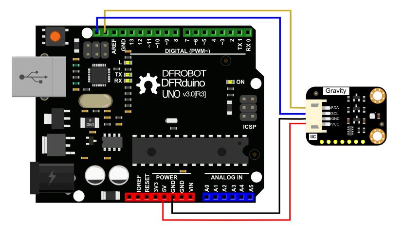
接线图
丝印
功能描述
SDA
I2C数据
SCL
I2C时钟
INT
中断输出引脚
SCK
SPI-CLK
SDI
SPI-MOSI
CSB
SPI-CS
SDO
SPI-MISO/I2C地址选择
GND
电源负极
VCC
电源正极
使用教程
目标:测出当前环境下的大气压强和温度值,计算出模块当前所在环境的海拔高度
准备
硬件
1 x Arduino UNO控制板
1 x Gravity I2C BMP388 温度&气压计
若干 杜邦线
软件
Arduino IDE 点击下载Arduino IDE
接线图
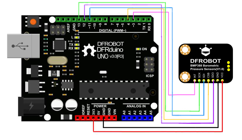
连接模块与UNO主板(通过I2C接口),按照如下图的方式连接。 连接模块与UNO主板(通过SPI接口),按照如下图的方式连接(csPin可设置为任意数字引脚)。
 样例代码2
使用SPI通讯
/*!
* @file interruptDataDrdy.ino
* @brief Demonstrate ready data (temperature/pressure) interrupt
* @details When measured data, the sensor will generate a 2.5 ms pulse signal by INT in the non-interrupt
* [url=home.php?mod=space&uid=821650]@N[/url] register locked state.
* @copyright Copyright (c) 2010 DFRobot Co.Ltd (http://www.dfrobot.com)
* @license The MIT License (MIT)
* @author [qsjhyy]([email protected])
* @version V1.0
* @date 2021-04-30
* @url https://github.com/DFRobot/DFRobot_BMP3XX
*/
#include
/**
* Select chip version BMP388/BMP390L
* Select I2C communication interface, please comment out SPI interface.
* I2C communication address settings: eSDOGND: connect SDO pin to GND, I2C address is 0×76 now.
* eSDOVDD: Connect SDO pin to VDDIO (3v3), I2C address is 0×77 now
* Notice: If using Gravity products, default I2C communication address is: 0×77(eSDOVDD)
*/
//DFRobot_BMP388_I2C sensor(&Wire, sensor.eSDOVDD);
//DFRobot_BMP390L_I2C sensor(&Wire, sensor.eSDOVDD);
/**
* Select the chip version BMP388/BMP390L
* Select I2C communication interface, please comment out SPI interface.
* Set up digital pin according to the on-board pin connected with SPI chip-select pin.
* Notice: csPin used here is D3 digital pin on ESP32, other non-conflicting pins can also be selected
* as external interrupt pins.
*/
uint8_t csPin = 4;
DFRobot_BMP388_SPI sensor(&SPI, csPin);
// DFRobot_BMP390L_SPI sensor(&SPI, csPin);
/* If you do not need to eliminate the absolute difference of measurement, please comment the following line */
#define CALIBRATE_ABSOLUTE_DIFFERENCE
/* Interrupt flag */
volatile uint8_t flag = 0;
/* External interrupt flag */
void interrupt()
{
if(flag ==0){
flag = 1;
}
}
void setup(void)
{
Serial.begin(115200);
int rslt;
while( ERR_OK != (rslt = sensor.begin()) ){
if(ERR_DATA_BUS == rslt){
Serial.println("Data bus error!!!");
}else if(ERR_IC_VERSION == rslt){
Serial.println("Chip versions do not match!!!");
}
delay(3000);
}
Serial.println("Begin ok!");
/**
* Interrupt configuration
* mode The interrupt mode needs to set. The following modes add up to mode:
* Interrupt pin output mode: eINTPinPP: Push pull, eINTPinOD: Open drain
* Interrupt pin active level: eINTPinActiveLevelLow: Active low, eINTPinActiveLevelHigh: Active high
* Register interrupt latch: eINTLatchDIS: Disable, eINTLatchEN: Enable
* FIFO water level reached interrupt: eIntFWtmDis: Disable, eIntFWtmEn: Enable
* FIFO full interrupt: eINTFFullDIS: Disable, eINTFFullEN: Enable
* Interrupt pin initial (invalid, non-interrupt) level: eINTInitialLevelLOW: Low, eINTInitialLevelHIGH: High
* Temperature/pressure data ready interrupt: eINTDataDrdyDIS: Disable, eINTDataDrdyEN: Enable
* Notice: In non-latching mode (eINTLatchDIS), interrupt signal is 2.5 ms pulse signal
* Note: When using eINTPinActiveLevelLow (Active low interrupt pin), you need to use eINTInitialLevelHIGH (Initial
* level of interrupt pin is high). Please use “FALLING” to trigger the following interrupt.
* When using eINTPinActiveLevelHigh (Active low interrupt pin), you need to use eINTInitialLevelLOW (Initial
* level of interrupt pin is high). Please use “RISING” to trigger the following interrupt.
*/
sensor.setINTMode(sensor.eINTPinPP |
sensor.eINTPinActiveLevelHigh |
sensor.eINTLatchDIS |
sensor.eIntFWtmDis |
sensor.eINTFFullDIS |
sensor.eINTInitialLevelLOW |
sensor.eINTDataDrdyEN);
delay(100);
#ifdef CALIBRATE_ABSOLUTE_DIFFERENCE
/**
* Calibrate the sensor according to the current altitude
* In this example, we use an altitude of 540 meters in Wenjiang District of Chengdu (China).
* Please change to the local altitude when using it.
* If this interface is not called, the measurement data will not eliminate the absolute difference
* Note: This interface is only valid for the first call
*/
if( sensor.calibratedAbsoluteDifference(540.0) ){
Serial.println("Absolute difference base value set successfully!");
}
#endif
#if defined(ESP32) || defined(ESP8266)
// D6 pin is used as interrupt pin by default, other non-conflicting pins can also be selected as external interrupt pins.
attachInterrupt(digitalPinToInterrupt(D6)/* Query the interrupt number of the D6 pin */,interrupt,CHANGE);
#elif defined(Arduino_SAM_ZERO)
// Pin 5 is used as interrupt pin by default, other non-conflicting pins can also be selected as external interrupt pins
attachInterrupt(digitalPinToInterrupt(5)/* Query the interrupt number of the 5 pin */,interrupt,CHANGE);
#else
/* The Correspondence Table of AVR Series Arduino Interrupt Pins And Terminal Numbers
* ---------------------------------------------------------------------------------------
* | | DigitalPin | 2 | 3 | |
* | Uno, Nano, Mini, other 328-based |--------------------------------------------|
* | | Interrupt No | 0 | 1 | |
* |-------------------------------------------------------------------------------------|
* | | Pin | 2 | 3 | 21 | 20 | 19 | 18 |
* | Mega2560 |--------------------------------------------|
* | | Interrupt No | 0 | 1 | 2 | 3 | 4 | 5 |
* |-------------------------------------------------------------------------------------|
* | | Pin | 3 | 2 | 0 | 1 | 7 | |
* | Leonardo, other 32u4-based |--------------------------------------------|
* | | Interrupt No | 0 | 1 | 2 | 3 | 4 | |
* |--------------------------------------------------------------------------------------
* ---------------------------------------------------------------------------------------------------------------------------------------------
* The Correspondence Table of micro:bit Interrupt Pins And Terminal Numbers
* ---------------------------------------------------------------------------------------------------------------------------------------------
* | micro:bit | DigitalPin |P0-P20 can be used as an external interrupt |
* | (When using as an external interrupt, |---------------------------------------------------------------------------------------------|
* |no need to set it to input mode with pinMode)|Interrupt No|Interrupt number is a pin digital value, such as P0 interrupt number 0, P1 is 1 |
* |-------------------------------------------------------------------------------------------------------------------------------------------|
*/
attachInterrupt(/*Interrupt No*/1,interrupt,CHANGE); // Open the external interrupt 0, connect INT1/2 to the digital pin of the main control:
// UNO(2), Mega2560(2), Leonardo(3), microbit(P0).
#endif
/* Get the sampling period of the current measurement mode, unit: us */
float sampingPeriodus = sensor.getSamplingPeriodUS();
Serial.print("samping period : ");
Serial.print(sampingPeriodus);
Serial.println(" us");
/* Get the sampling frequency of the current measurement mode, unit: Hz */
float sampingFrequencyHz = 1000000 / sampingPeriodus;
Serial.print("samping frequency : ");
Serial.print(sampingFrequencyHz);
Serial.println(" Hz");
Serial.println();
delay(1000);
}
void loop()
{
if(flag == 1){
flag = 0;
/* When data is ready and the interrupt is triggered, read altitude, unit: m */
float altitude = sensor.readAltitudeM();
Serial.print("Altitude : ");
Serial.print(altitude);
Serial.println(" m");
}
}
Mind+ 上传模式编程
下载及安装软件。下载地址:https://www.mindplus.cc 详细教程:Mind+基础wiki教程-软件下载安装
切换到“上传模式”。 详细教程:Mind+基础wiki教程-上传模式编程流程
“扩展”中选择“主控板”中的“Arduino Uno”。 “扩展”“传感器”中搜索选择“BMP388模块”,详细教程:Mind+基础wiki教程-加载扩展库流程
进行编程,程序如下图:
菜单“连接设备”,“上传到设备”
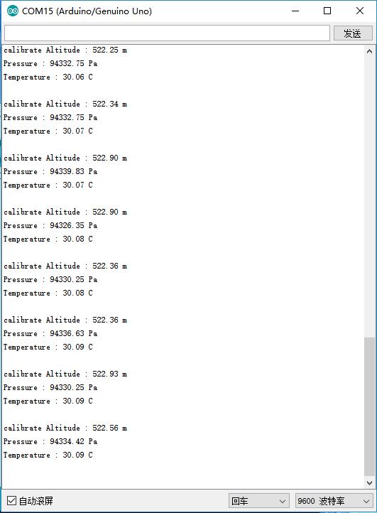
程序上传完毕后,打开串口即可看到数据输出。详细教程:Mind+基础wiki教程-串口打印
样例代码2
使用SPI通讯
/*!
* @file interruptDataDrdy.ino
* @brief Demonstrate ready data (temperature/pressure) interrupt
* @details When measured data, the sensor will generate a 2.5 ms pulse signal by INT in the non-interrupt
* [url=home.php?mod=space&uid=821650]@N[/url] register locked state.
* @copyright Copyright (c) 2010 DFRobot Co.Ltd (http://www.dfrobot.com)
* @license The MIT License (MIT)
* @author [qsjhyy]([email protected])
* @version V1.0
* @date 2021-04-30
* @url https://github.com/DFRobot/DFRobot_BMP3XX
*/
#include
/**
* Select chip version BMP388/BMP390L
* Select I2C communication interface, please comment out SPI interface.
* I2C communication address settings: eSDOGND: connect SDO pin to GND, I2C address is 0×76 now.
* eSDOVDD: Connect SDO pin to VDDIO (3v3), I2C address is 0×77 now
* Notice: If using Gravity products, default I2C communication address is: 0×77(eSDOVDD)
*/
//DFRobot_BMP388_I2C sensor(&Wire, sensor.eSDOVDD);
//DFRobot_BMP390L_I2C sensor(&Wire, sensor.eSDOVDD);
/**
* Select the chip version BMP388/BMP390L
* Select I2C communication interface, please comment out SPI interface.
* Set up digital pin according to the on-board pin connected with SPI chip-select pin.
* Notice: csPin used here is D3 digital pin on ESP32, other non-conflicting pins can also be selected
* as external interrupt pins.
*/
uint8_t csPin = 4;
DFRobot_BMP388_SPI sensor(&SPI, csPin);
// DFRobot_BMP390L_SPI sensor(&SPI, csPin);
/* If you do not need to eliminate the absolute difference of measurement, please comment the following line */
#define CALIBRATE_ABSOLUTE_DIFFERENCE
/* Interrupt flag */
volatile uint8_t flag = 0;
/* External interrupt flag */
void interrupt()
{
if(flag ==0){
flag = 1;
}
}
void setup(void)
{
Serial.begin(115200);
int rslt;
while( ERR_OK != (rslt = sensor.begin()) ){
if(ERR_DATA_BUS == rslt){
Serial.println("Data bus error!!!");
}else if(ERR_IC_VERSION == rslt){
Serial.println("Chip versions do not match!!!");
}
delay(3000);
}
Serial.println("Begin ok!");
/**
* Interrupt configuration
* mode The interrupt mode needs to set. The following modes add up to mode:
* Interrupt pin output mode: eINTPinPP: Push pull, eINTPinOD: Open drain
* Interrupt pin active level: eINTPinActiveLevelLow: Active low, eINTPinActiveLevelHigh: Active high
* Register interrupt latch: eINTLatchDIS: Disable, eINTLatchEN: Enable
* FIFO water level reached interrupt: eIntFWtmDis: Disable, eIntFWtmEn: Enable
* FIFO full interrupt: eINTFFullDIS: Disable, eINTFFullEN: Enable
* Interrupt pin initial (invalid, non-interrupt) level: eINTInitialLevelLOW: Low, eINTInitialLevelHIGH: High
* Temperature/pressure data ready interrupt: eINTDataDrdyDIS: Disable, eINTDataDrdyEN: Enable
* Notice: In non-latching mode (eINTLatchDIS), interrupt signal is 2.5 ms pulse signal
* Note: When using eINTPinActiveLevelLow (Active low interrupt pin), you need to use eINTInitialLevelHIGH (Initial
* level of interrupt pin is high). Please use “FALLING” to trigger the following interrupt.
* When using eINTPinActiveLevelHigh (Active low interrupt pin), you need to use eINTInitialLevelLOW (Initial
* level of interrupt pin is high). Please use “RISING” to trigger the following interrupt.
*/
sensor.setINTMode(sensor.eINTPinPP |
sensor.eINTPinActiveLevelHigh |
sensor.eINTLatchDIS |
sensor.eIntFWtmDis |
sensor.eINTFFullDIS |
sensor.eINTInitialLevelLOW |
sensor.eINTDataDrdyEN);
delay(100);
#ifdef CALIBRATE_ABSOLUTE_DIFFERENCE
/**
* Calibrate the sensor according to the current altitude
* In this example, we use an altitude of 540 meters in Wenjiang District of Chengdu (China).
* Please change to the local altitude when using it.
* If this interface is not called, the measurement data will not eliminate the absolute difference
* Note: This interface is only valid for the first call
*/
if( sensor.calibratedAbsoluteDifference(540.0) ){
Serial.println("Absolute difference base value set successfully!");
}
#endif
#if defined(ESP32) || defined(ESP8266)
// D6 pin is used as interrupt pin by default, other non-conflicting pins can also be selected as external interrupt pins.
attachInterrupt(digitalPinToInterrupt(D6)/* Query the interrupt number of the D6 pin */,interrupt,CHANGE);
#elif defined(Arduino_SAM_ZERO)
// Pin 5 is used as interrupt pin by default, other non-conflicting pins can also be selected as external interrupt pins
attachInterrupt(digitalPinToInterrupt(5)/* Query the interrupt number of the 5 pin */,interrupt,CHANGE);
#else
/* The Correspondence Table of AVR Series Arduino Interrupt Pins And Terminal Numbers
* ---------------------------------------------------------------------------------------
* | | DigitalPin | 2 | 3 | |
* | Uno, Nano, Mini, other 328-based |--------------------------------------------|
* | | Interrupt No | 0 | 1 | |
* |-------------------------------------------------------------------------------------|
* | | Pin | 2 | 3 | 21 | 20 | 19 | 18 |
* | Mega2560 |--------------------------------------------|
* | | Interrupt No | 0 | 1 | 2 | 3 | 4 | 5 |
* |-------------------------------------------------------------------------------------|
* | | Pin | 3 | 2 | 0 | 1 | 7 | |
* | Leonardo, other 32u4-based |--------------------------------------------|
* | | Interrupt No | 0 | 1 | 2 | 3 | 4 | |
* |--------------------------------------------------------------------------------------
* ---------------------------------------------------------------------------------------------------------------------------------------------
* The Correspondence Table of micro:bit Interrupt Pins And Terminal Numbers
* ---------------------------------------------------------------------------------------------------------------------------------------------
* | micro:bit | DigitalPin |P0-P20 can be used as an external interrupt |
* | (When using as an external interrupt, |---------------------------------------------------------------------------------------------|
* |no need to set it to input mode with pinMode)|Interrupt No|Interrupt number is a pin digital value, such as P0 interrupt number 0, P1 is 1 |
* |-------------------------------------------------------------------------------------------------------------------------------------------|
*/
attachInterrupt(/*Interrupt No*/1,interrupt,CHANGE); // Open the external interrupt 0, connect INT1/2 to the digital pin of the main control:
// UNO(2), Mega2560(2), Leonardo(3), microbit(P0).
#endif
/* Get the sampling period of the current measurement mode, unit: us */
float sampingPeriodus = sensor.getSamplingPeriodUS();
Serial.print("samping period : ");
Serial.print(sampingPeriodus);
Serial.println(" us");
/* Get the sampling frequency of the current measurement mode, unit: Hz */
float sampingFrequencyHz = 1000000 / sampingPeriodus;
Serial.print("samping frequency : ");
Serial.print(sampingFrequencyHz);
Serial.println(" Hz");
Serial.println();
delay(1000);
}
void loop()
{
if(flag == 1){
flag = 0;
/* When data is ready and the interrupt is triggered, read altitude, unit: m */
float altitude = sensor.readAltitudeM();
Serial.print("Altitude : ");
Serial.print(altitude);
Serial.println(" m");
}
}
Mind+ 上传模式编程
下载及安装软件。下载地址:https://www.mindplus.cc 详细教程:Mind+基础wiki教程-软件下载安装
切换到“上传模式”。 详细教程:Mind+基础wiki教程-上传模式编程流程
“扩展”中选择“主控板”中的“Arduino Uno”。 “扩展”“传感器”中搜索选择“BMP388模块”,详细教程:Mind+基础wiki教程-加载扩展库流程
进行编程,程序如下图:
菜单“连接设备”,“上传到设备”
程序上传完毕后,打开串口即可看到数据输出。详细教程:Mind+基础wiki教程-串口打印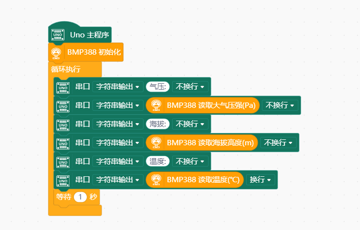 Mind+ Python模式编程(行空板)
Mind+Python模式为完整Python编程,因此需要能运行完整Python的主控板,此处以行空板为例说明 连接图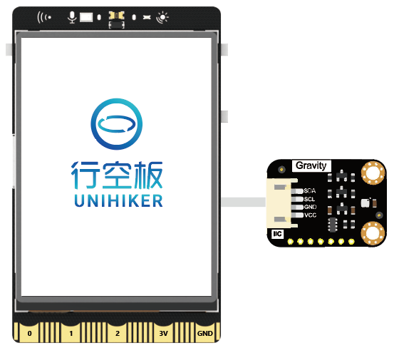 操作步骤
操作步骤
1、下载及安装官网最新软件。下载地址:https://www.mindplus.cc 详细教程:Mind+基础wiki教程-软件下载安装 2、切换到“Python模式”。“扩展”中选择“官方库”中的“行空板”和“pinpong库”中的”pinpong初始化“和“BMP388气压温度传感器。切换模式和加载库的详细操作链接 3、进行编程 4、连接行空板,程序点击运行后,可在终端查看数据。行空板官方文档-行空板快速上手教程 (unihiker.com)
以pinpong库为例,行空板官方文档-行空板快速上手教程 (unihiker.com) # -*- coding: UTF-8 -*- # MindPlus # Python from pinpong.libs.dfrobot_bmp388 import BMP388 from pinpong.board import Board import time Board().begin() bmp = BMP388() while True: print("大气压强:") print(bmp.pressure_pa()) print("海拔高度:") print(bmp.cal_altitude_m()) print("温度:") print(bmp.temp_C()) time.sleep(1) 常见问题1.此传感器如何和UNO SPI通信? 参考此贴:https://mc.dfrobot.com.cn/thread-316875-1-1.html 2.禁用温度采集后,高度(气压)采集数据会漂移(以一定速度变大或变小,明显超过正常范围且停不下来)? 温度本来就是为了校准气压的,测量气压的时候,不能禁用温度采集。 更多问题及有趣的应用,可以 访问论坛 进行查阅或发帖。 更多 原理图 BMP388数据手册 |


 DFRobot商城购买链接
【本文地址】
今日新闻 |
推荐新闻 |