毕业设计 |
您所在的位置:网站首页 › 汽车定位追踪器软件 › 毕业设计 |
毕业设计
|
文章目录
0 前言1 简介2 主要器件3 实现效果4 硬件设计Maduino Zero A9G GPRS/GPSk开发板这款低功耗A9G使用SIM800/900和NEO-6M GPS模块的基于Arduino的GPS跟踪系统
5 软件说明使用Arduino的基于GPS+GSM的车辆跟踪系统GPS+GSM的车辆跟踪系统的代码
6 最后
0 前言
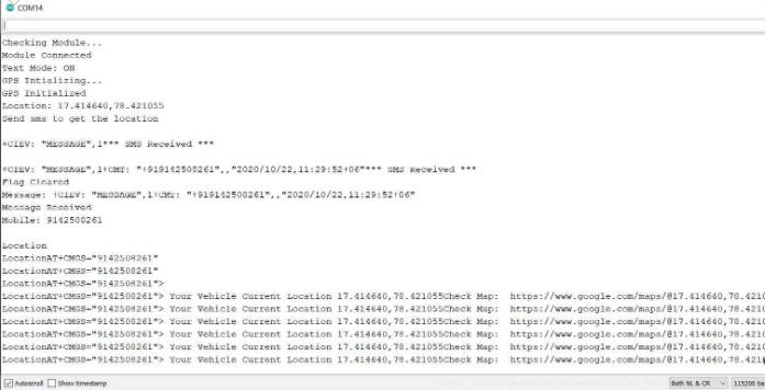
🔥 这两年开始毕业设计和毕业答辩的要求和难度不断提升,传统的毕设题目缺少创新和亮点,往往达不到毕业答辩的要求,这两年不断有学弟学妹告诉学长自己做的项目系统达不到老师的要求。 为了大家能够顺利以及最少的精力通过毕设,学长分享优质毕业设计项目,今天要分享的是 🚩 基于单片机与GPS+GMS的车辆定位跟踪系统 🥇学长这里给一个题目综合评分(每项满分5分) 难度系数:4分工作量:4分创新点:3分🧿 选题指导, 项目分享: https://gitee.com/dancheng-senior/project-sharing-1/blob/master/%E6%AF%95%E8%AE%BE%E6%8C%87%E5%AF%BC/README.md 1 简介本项目使用Arduino开发板制作基于GPS和GSM的车辆跟踪系统。市场上大多数车辆跟踪系统的价格都比较高。所以,我决定自制一套跟踪系统。车辆跟踪系统会将位置连同谷歌地图坐标一起发送到手机,您可以随时请求位置并在手机上的谷歌地图上查看具体位置。 与双向GPS通信系统相比,这是一种更便宜的解决方案,双向GPS通信系统通过GPS卫星进行双向通信。本文仅使用一个GPS设备,然后使用GSM调制解调器实现双向通信。GSM调制解调器使用2G网络,用于设备和手机之间的通信。 2 主要器件该项目使用了GSM/GPRS/GPS模块A9G。该设备非常小,可以安装在任何地方,并且可以使用3.7V锂离子电池进行操作。该电路板基于Atmel的32位ATSAMD21控制器,可以使用Arduino IDE进行编程。 还可以使用Arduino UNO开发板和Neo-6M GPS模块以及SIM800/900 GSM模块来制作这个项目。但这会使设备尺寸变大。如果您想使用4G连接,您可以使用SIM7600 4G LTE调制解调器模块。 第一种方法使用的组件列表 Maduino Zero GPRS/GPS开发板3.7V、1000毫安锂离子电池第二种方法使用的组件列表 Arduino UNO开发板1602 LCD显示屏SIM800/900 GSM模块Neo-6M GPS模块10K电位器连接跳线面包板 3 实现效果可以发送短信以获取位置。因此,在您的手机上打开短信,然后输入Arduino Zero开发板中使用的SIM卡的电话号码。之后,输入“Location”一词,然后发送。
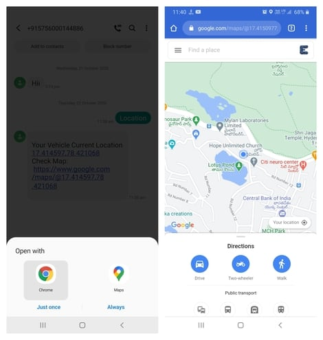
稍后,串口监视器将显示短信接收状态,并告知日期时间和手机号码。然后,您将在手机上收到一条带有纬度经度坐标的短信。同时您还将收到一个指向谷歌地图的链接。您可以单击该链接并使用谷歌地图打开。
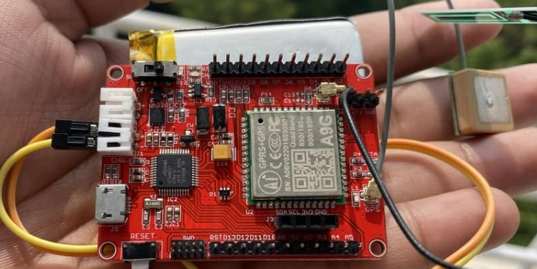
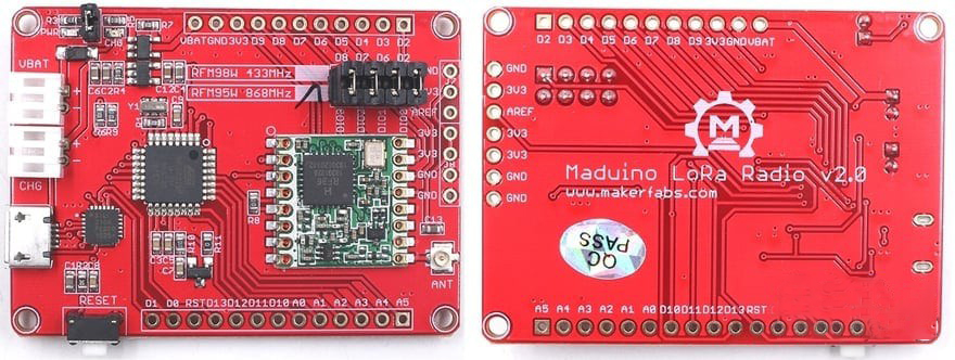
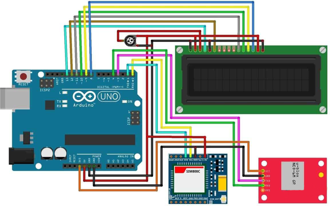
GSM+GPS+GPRS模块集成了32位Atmel的SAMD21微控制器。开发板的正面和背面如下图所示。 A9G GSM GPS开发板是由Ai-Thinker制造。该模块可通过Micro USB端口进行编程,并可通过3.7V锂离子电池供电。它有一个开关来打开和关闭。数字输入输出引脚可用于连接任何其他模块或传感器。 Arduino使用的是8位控制器,但该开发板使用的是32位Atmel ATSAMD21G18控制器,因此使得设备运行速度更快。它有一个电压调节器IC来调整电压。同样,有两根天线,一根是GSM天线,另一根是GPS天线。该模块一个2G调制解调器,因此根据频段只能使用2G的SIM卡。它还有一个Micro-SD端口。您还可以使用SD卡以文本格式保存数据。 使用SIM800/900和NEO-6M GPS模块的基于Arduino的GPS跟踪系统使用Arduino UNO开发板、SIM900或SIM800 GSM模块以及NEO-6M GPS模块也可以完成相同的项目。电路中还新增了一个LCD用于显示状态。 除了连接电池外,您不需要任何外部硬件部件。上面解释了所有的理论部分,现在让我们设置Arduino IDE。 Arduino IDE没有预装对SAMD开发板的支持。因此,您需要先将开发板添加到Arduino IDE。所以,转到板管理器查询Arduino Zero。
现在转到Tools菜单,在这里你会找到Arduino SAMD开发板。然后从列表中选择对应的串口号。 与其他GSM GPS模块的Arduino代码相比,它有点不同。AT命令AT+GPS=1打开电路板的GPS功能。AT+LOCATION =2命令检索GPS位置作为纬度和经度。 #include #define DEBUG true int PWR_KEY = 9; int RST_KEY = 6; int LOW_PWR_KEY = 5; String msg = String(""); int SmsContentFlag = 0; String mob; String loct; void setup() { pinMode(PWR_KEY, OUTPUT); pinMode(RST_KEY, OUTPUT); pinMode(LOW_PWR_KEY, OUTPUT); digitalWrite(RST_KEY, LOW); digitalWrite(LOW_PWR_KEY, HIGH); digitalWrite(PWR_KEY, HIGH); // String msg = String(""); // int SmsContentFlag = 0; SerialUSB.begin(115200); Serial1.begin(115200); //modulePowerOn(); delay(2000); SerialUSB.println("Checking Module..."); int i = 1; String res; while (i) { Serial1.println("AT"); while (Serial1.available() > 0) { if (Serial1.find("OK")) i = 0; } delay(500); } SerialUSB.println("Module Connected"); //GprsTextModeSMS(); SerialUSB.print("Text Mode: "); i = 1; while (i) { Serial1.println("AT+CMGF=1\r"); while (Serial1.available() > 0) { if (Serial1.find("OK")) i = 0; } delay(500); } SerialUSB.println("ON"); Serial1.println("AT+GPS=1"); SerialUSB.println("GPS Intializing..."); delay(5000); SerialUSB.println("GPS Initialized"); SerialUSB.flush(); i = 1; String str; while (i) { Serial1.println("AT+LOCATION=2"); delay(100); while (Serial1.available() = 0 ) { SerialUSB.println( "*** GPRS Shield registered on Mobile Network ***" ); GprsTextModeSMS(); } //EN: unsolicited message received when getting a SMS message if ( msg.indexOf( "+CIEV" ) >= 0 ) { SerialUSB.println( "*** SMS Received ***" ); } //EN: SMS store readed through UART (result of GprsReadSmsStore request) if ( msg.indexOf( "+CMT:" ) >= 0 ) { // EN: Next message will contains the BODY of SMS SmsContentFlag = 1; // EN: Following lines are essentiel to not clear the flag! //ClearGprsMsg(); return; } // EN: +CMGR message just before indicate that the following GRPS Shield message // (this message) will contains the SMS body if ( SmsContentFlag == 1 ) { SerialUSB.println( "*** SMS MESSAGE CONTENT ***" ); SerialUSB.println( msg ); SerialUSB.println( "*** END OF SMS MESSAGE ***" ); //ProcessSms( msg ); } /*ClearGprsMsg(); //EN: Always clear the flag SmsContentFlag = 0; */ } 6 最后 |
 以下是使用SIM800/900 GSM模块和NEO-6M GPS模块的跟踪系统的代码。这段代码稍微小一点,需要稍微修改一下,比如更换手机号。
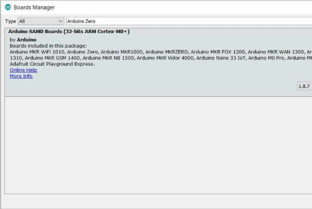 然后安装32 bit ARM Cortex Board。在硬件部分,将Micro USB电缆连接到Maduino Zero开发板,电缆的另一端连接到计算机的USB端口。
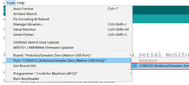
【本文地址】