桥式起重机桥架结构设计(说明书+CAD图纸+SolidWorks三维图+开题报告+任务书+外文翻译) |
您所在的位置:网站首页 › 梁的结构设计 › 桥式起重机桥架结构设计(说明书+CAD图纸+SolidWorks三维图+开题报告+任务书+外文翻译) |
桥式起重机桥架结构设计(说明书+CAD图纸+SolidWorks三维图+开题报告+任务书+外文翻译)
|
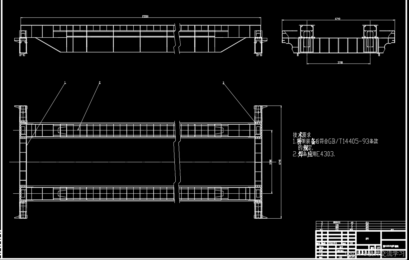
桥式起重机桥架结构设计 摘 要 桥式起重机主要由机械部分、金属结构和电气三大部分所组成。机械部分是指起升、运行、变幅和旋转等机构,还有起升机构,金属结构是构成起重机械的躯体,是安装各机构和支托它们全部重量的主体部分。电气是起重机械动作的能源,各机构都是单独驱动的。 构成桥式起重机的主要金属结构部分是桥架,它横架在车间两侧吊车梁的轨道上,并沿轨道前后运行。本文根据桥式起重机起重量和跨度的要求,依据《起重机设计规范》、GB/T3811-2008等标准,设计计算了50/10t×25.5m偏轨双梁桥式起重机桥架结构的设计方案,并绘制了相关的三维结构图以及二维结构图。 本文首先从整体设计出发,依次设计计算了50/10t×25.5m双梁桥式起重机的主端梁结构的主要机构部件。选取了大车车轮,小车车轮,小车轨道等起重机主要零部件。设计了符合经济梁要求的桥架结构,并校核了起重机桥架在危险截面处的强度和刚度等力学性能参数。设计过程中,桥架采用全偏轨箱形主梁、箱形端梁的双梁结构。桥架刚性好,制作方便。考虑到起重机整机和各个机构零部件的合理布置,作者通过计算多组数据来选择最优结果。达到了起重机各机构布置紧凑性和合理性的目的,从而优化了起重机整机的性能。 本设计所选的大部分零件均具有通用化、标准化、系列化的特点,主要技术参数均符合ISO标准,贯彻了国家以及起重机行业的所有最新颁布的各项标准。所设计的起重机整体安全、可靠。 关键词: 桥式起重机,桥架结构,金属结构,三维模型图,二维工程图 The design of the structure of bridge crane Abstract Because the crane running at high altitude, scope of work can sweep the whole plant construction area, has a very important and irreplaceable role. Therefore welcomed by users, has been great development. Bridge crane is mainly composed of the mechanical parts, metal structure and electrical three parts. The mechanical part is lifting, running, amplitude and rotating mechanism, metal structure is composed of lifting body, is the main installation of various institutions and support them all the weight of the part. Electric is a lifting movement of energy, the agencies are separately driven. Constitute the main bridge crane metal structure part is the bridge, it is in the workshop crane beam transverse frame on both sides of the track, and along the track before and after operation. According to the requirements of the bidding documents of an enterprise and the design specification of crane GB/T3811-2008, performance evaluations of 50/10t×25.5m double beam bridge crane were calculated, and draw the three-dimensional structure and two-dimensional structure diagram. At the beginning of this article, the main structure of 50/10t×25.5m double beam bridge crane were calculated. Select the carts wheels, trolley wheels, trolley tracks and other major components cranes.The structure of the bridge was designed to achieve the requirement of economical efficiency, and also intensity and stiffness was checked to make sure its safety. The double beam bridge structure includes the Crane Girder and the end carriage. This kind of structure has better stiffness and manufacturability. Considering the disposal of crane and different parts, the authors calculated through multiple data to select the optimal results. Finally, the goal of better crane performance and rationality and compactedness of all parts of crane was achieved. At last, most of the parts of the design characteristics of the selected are universal, standardized, serialized, the main technical parameters are in accordance with ISO standard, implement the state and all the latest promulgated crane industry standards. In one words, the safety and reliability of this Crane can be confirmed. key words:Bridge crane,The bridge structure,Metal structure,Three-dimensional model,The 2D engineering drawings 目录 第一章 绪论 1.1 课题的背景 1.2国内外桥式起重机现状与发展前景 1.2.1 国内起重机现状 1.2.2 国外起重机发展前景 1.3 本设计的主要内容、目标和方法 第二章 桥式起重机偏轨箱型双梁桥架总体设计 2.1 基本参数 2.2主梁尺寸 2.3端梁尺寸 2.4主、端梁的连接 2.5桥架结构与主、端梁截面示意图 第三章 主端梁的设计计算 3.1 主梁的计算 3.1.1载荷与内力计算 3.1.2动力效应系数 3.1.3惯性力计算 3.1.4偏斜运行侧向力 3.1.5 扭转载荷计算 3.1.6 内力 3.1.7强度 3.1.8主梁疲劳强度 3.1.9主梁稳定性 3.2 端梁计算 3.2.1载荷与内力 3.2.2 强度 3.2.3 疲劳强度 3.2.4 稳定性 3.2.5 端梁拼接 3.3 主梁与端梁的连接 第四章 校核计算 4.1 桥架的垂直刚度 4.1.1桥架的垂直静刚度 4.1.2垂直动刚度 4.2 桥架的水平刚度 4.2.1桥架的水平惯性位移 4.2.2水平动刚度 4.3 桥架拱度 第五章 桥架结构三维模型的建立 5.1端梁三维模型及二维工程图的建立 5.1.1端梁三维图的绘制 5.1.2端梁二维工程图的绘制 5.2主梁的绘制 5.2.1主梁三维图的绘制 5.2.2主梁二维工程图的绘制 5.3双梁桥架结构的装配及其二维工程图 5.3.1双梁桥架结构的装配 5.3.2双梁桥架结构的二维工程图绘制 第六章 总结 参考文献 致 谢 59 …………
|
【本文地址】