六自由度工业机器人设计【说明书(论文)+CAD图纸+SolidWorks三维图+任务书+开题报告】 |
您所在的位置:网站首页 › 机器人立体书 › 六自由度工业机器人设计【说明书(论文)+CAD图纸+SolidWorks三维图+任务书+开题报告】 |
六自由度工业机器人设计【说明书(论文)+CAD图纸+SolidWorks三维图+任务书+开题报告】
|
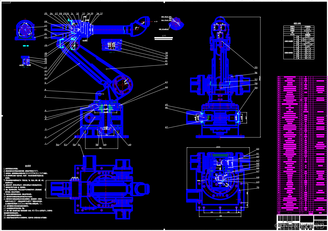
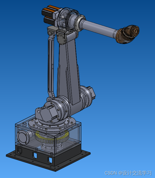
摘 要 六自由度工业机器人是一种高精度的自动化机械,具有高度的灵活性以及平稳性。所以在设计中我们应当注意其结构工艺的合理性,在材料选择上应当使其具有高强度和轻便的特性。本论文主要对搬运工业机器人的驱动方式及各轴的传动方案进行了设计,并对驱动运动的电动机进行了选型;在对其工作空间分析的基础上,对关键的零部件进行了受力分析及强度校核;根据其基本结构参数,利用Solidworks2013软件进行了三维图形的绘制,并用CAD绘制了装配图及部分关键零件图。 关键词: 工业机器人;结构设计;传动方案设计;受力分析;强度校核 Abstract Six degree of freedom industrial robot is a kind of automatic machine with high accuracy, with high degree of flexibility and stability.. So in the design we should pay attention to the rationality of the structure and technology, in the choice of materials should be so that it has high strength and lightweight, this paper mainly for the handling of industrial robot total drive way and the axis of the transmission scheme design, and the drive motor selection; in work space analysis based on the kinematics calculation, of key parts were stress analysis and strength check; according to the basic structure parameters using software Solidworks2013 of 3D graphics rendering, and mapping with CAD assembly drawing and part of the key parts of the map. KeyWords:Industrial robots; Structural design; Transmission design; Force analysis;Intensity verification 目 录 第一章 绪论……………………………………………………………………………… 1 1.1 工业机器人概述……………………………………………………………………1 1.2 课题研究背景及意义………………………………………………………………1 1.3 国内外研究现状及发展趋势………………………………………………………2 1.3.1 国内研究现状…………………………………………………………………3 1.3.2 国外发展趋势…………………………………………………………………4 1.4 工业机器人相关技术………………………………………………………………5 1.5 本文主要内容………………………………………………………………………5 第二章 总体方案与传动机构设计………………………………………………… 6 2.1 总体方案设计与分析……………………………………………………………… 6 2.1.1 方案要求…………………………………………………………………… 6 2.1.2 机构选型…………………………………………………………………… 7 2.1.3 驱动方式选择……………………………………………………………… 8 2.2 传动方案的初步设计……………………………………………………………… 9 2.2.1 腕关节传动机构设计……………………………………………………… 10 2.2.2 小臂传动机构……………………………………………………………… 10 2.2.3 大臂传动机构……………………………………………………………… 11 2.2.4 腰身传动机构……………………………………………………………… 12 2.3 机器人部分技术参数 …………………………………………………………… 10 第三章 工作空间分析及计算……………………………………………………… 12 3.1 工作空间…………………………………………………………………………12 3.2 工作空间与机器人结构尺寸的相关性…………………………………………12 3.3 分析………………………………………………………………………………14 第四章 结构设计…………………………………………………………………… 15 4.1 传动方案的设计………………………………………………………………… 15 4.2 手腕传动………………………………………………………………………… 15 4.3 腰部………………………………………………………………………………16 4.3.1 腕部的设计要求…………………………………………………………… 16 4.3.2 腕部结构…………………………………………………………………… 16 4.4 手臂……………………………………………………………………………… 17 4.4.1 手臂作用概述……………………………………………………………… 17 4.4.2 电机选择…………………………………………………………………… 17 4.5 传动结构设计计算……………………………………………………………… 20 4.5.1 腰部设计…………………………………………………………………… 20 4.5.2 大臂设计…………………………………………………………………… 21 4.5.3 小臂设计…………………………………………………………………… 22 第五章 关键零部件的校核……………………………………………………………24 5.1 腕部中心轴的结构设计与校核……………………………………………………24 5.1.1 腕部中心轴的结构设计 …………………………………………………… 25 5.1.2 腕部中心轴的强度校核 …………………………………………………… 25 5.2 连杆传动轴的结构设计与校核 ………………………………………………… 28 5.2.1 连杆传动轴的结构设计…………………………………………………… 28 5.2.2 连杆传动轴的强度校核…………………………………………………… 29 5.3 手腕齿轮连接轴的结构设计与校核…………………………………………… 28 5.4 手腕齿轮连接轴2的结构设计与校核………………………………………… 29 5.5 回转底盘与腰部主轴连接螺钉的校核………………………………………… 29 5.6 部分三维图形的绘制…………………………………………………………… 30 第六章 总结 …………………………………………………………………………… 35 参考文献 ………………………………………………………………………………… 36 致谢 ………………………………………………………………………………………37 ………… …………
|
【本文地址】