在Proteus中模拟SD卡模块 |
您所在的位置:网站首页 › 怎么用proteus仿真arduino › 在Proteus中模拟SD卡模块 |
在Proteus中模拟SD卡模块
|
在本主题中,我们将讨论如何开始使用 Arduino 和 SD 卡(microSD 卡)的简单 proteus 模拟。 我将在本主题的后面部分解释如何阅读有关 SD 卡的信息,以使您熟悉该概念。在本例中,我们将学习如何使用winimage软件创建映像文件,并使用winimage和SD 库选择某些参数,如卷类型、可用空间和其他信息,并通过串行端口发送。然后我们将模仿 proteus 中的示例,以达到类似于实际实验的最佳所需结果。 Arduino 的 SD 卡库非常出色,它使与 SD 卡的交互非常简单。使用 Arduino SD 库可以读取和写入 SD 卡。它基于 William Greiman 的 sdfatlib。在普通 SD 和 SDHC 卡上,该库支持 FAT16 和 FAT32 文件系统。对于文件名,它使用 8.3 短名称。 SPI 用于在微控制器和 SD 卡之间进行通信,它位于数字引脚 11、12 和 13(在大多数 Arduino 板上)或 50、51 和 52(在某些 Arduino 板上)(Arduino Mega)。还需要第二个引脚来选择 SD 卡。可以使用硬件 SS 引脚(大多数 Arduino 板上的引脚 10 或 Mega 上的引脚 53)或 SD.begin() 调用中指定的另一个引脚。 所需组件 硬件 Arduino板 具有 FAT16 或 FAT32 文件系统的 SD 卡 LM35 虚拟终端(作为串行监视器) PCF8574 I2C液晶接口模块 LM016L (LCD) 显示器 R1 & R2 = 10k 欧姆软件 变形虫 Arduino IDE Winimage1.先决条件练习 在我们开始进行实际零件仿真之前,我们将通过简单的下载、安装和设置 Arduino IDE 和 Proteus 库的练习来热身。 一世。安装 Winimage 我们的第一步是从 Internet 下载 winimage 并将下载路径设置为便于以后访问。根据系统要求,从官网选择相应的 latest.exe 文件。 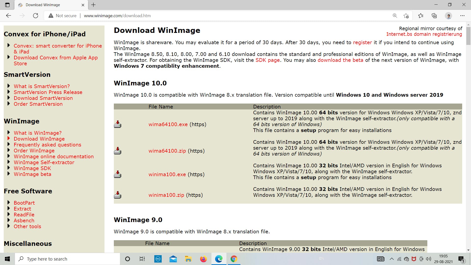
一世。在 IDE 中添加 SD 卡库 现在我们将从 IDE 下载 SD 库。请按照下图所示的步骤了解有关如何下载适用于 Arduino IDE 的 SD 库的更多信息。我们将使用这个库来为 Arduino 编程 SD 卡模块以存储和检索数据。 第 1 步:打开 Arduino IDE 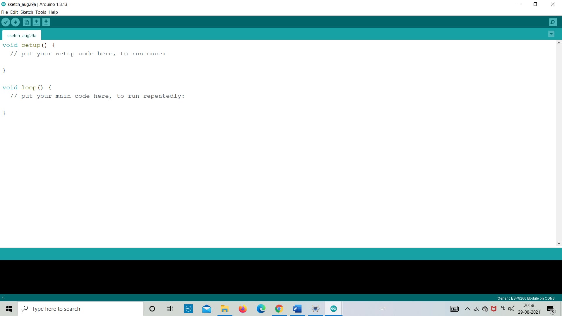
第 2 步:转到“草图”>>“包含库”>>“管理库” 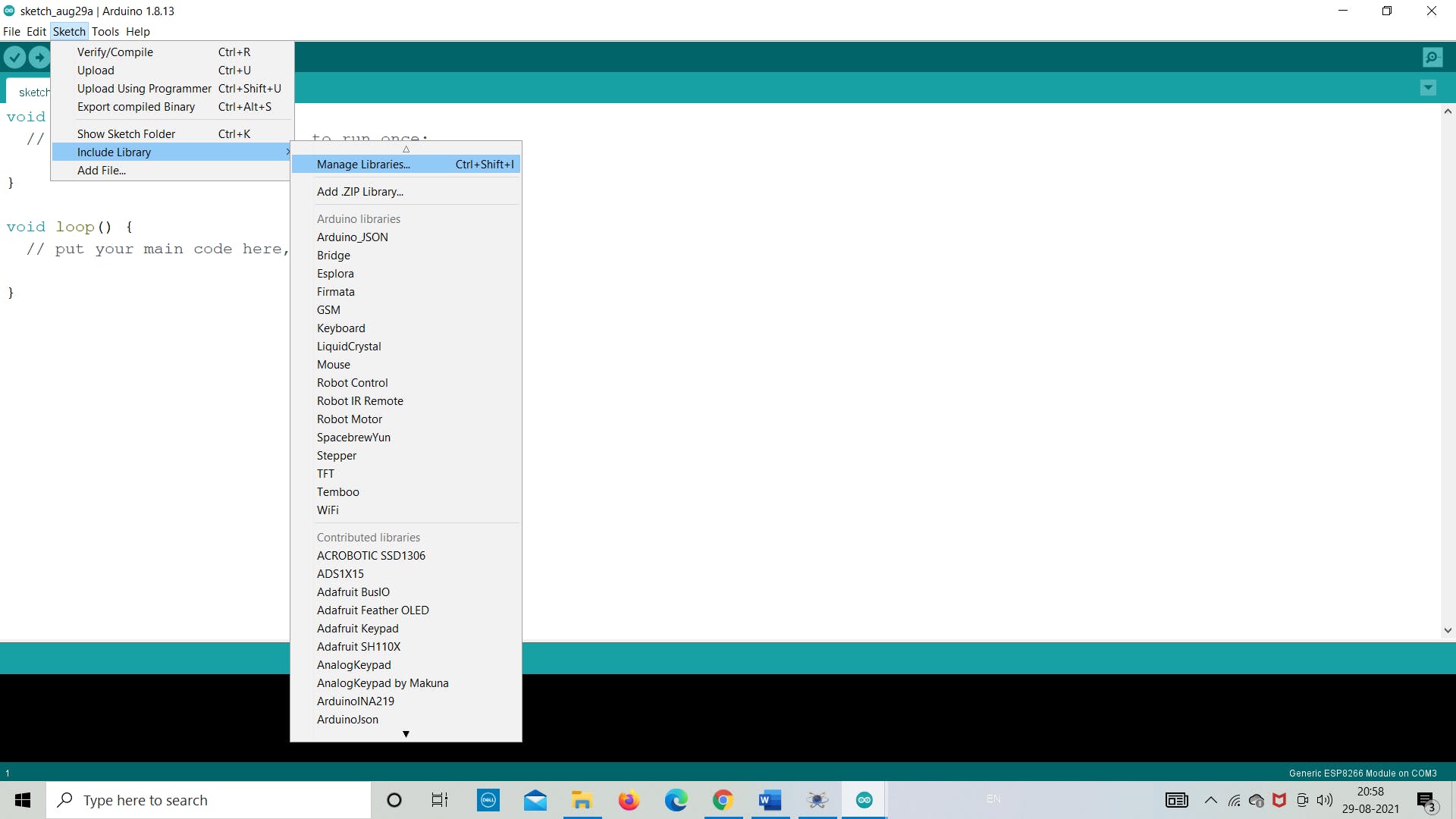
第 3 步:在搜索栏中搜索“SD”并从那里“安装” 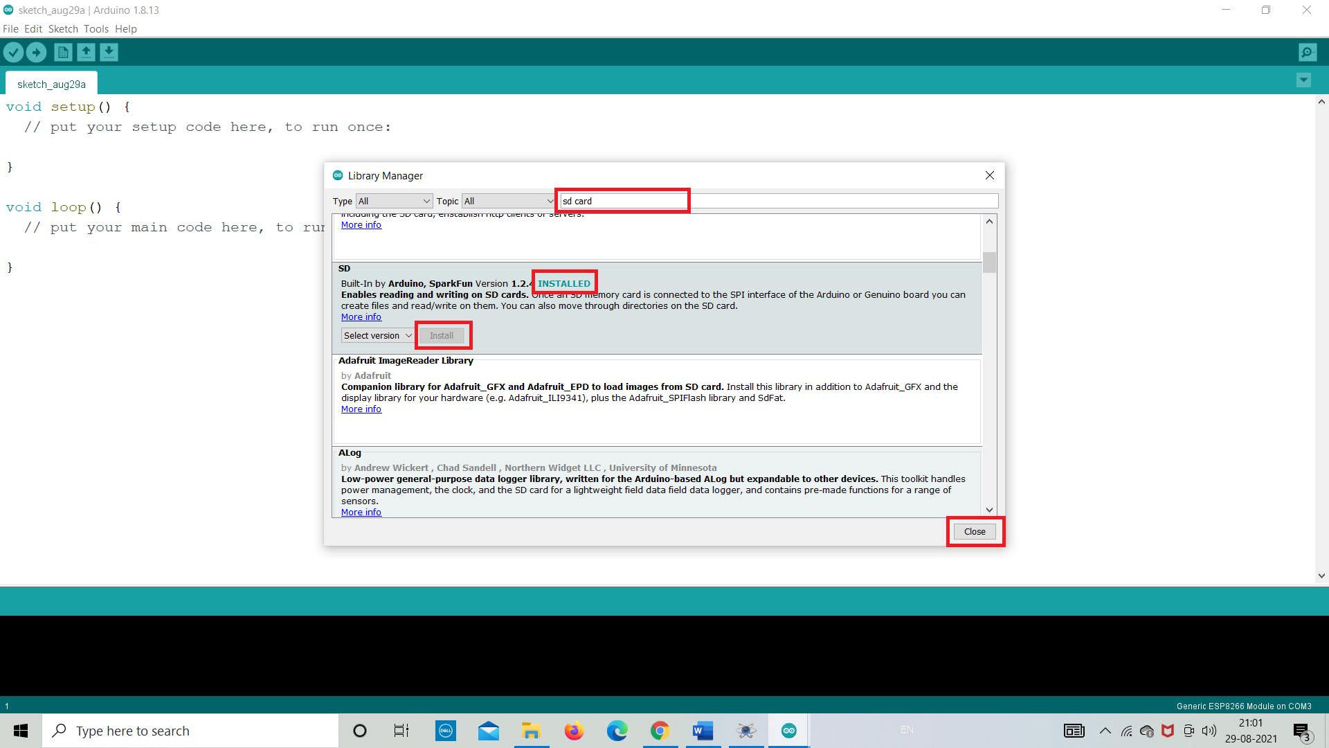
ii. 创建 Winimage 映像文件 下一步是使用 winimge.exe 软件创建图像文件。在这里,我们将从下载的文件夹中打开它,并将创建 2 MB 大小的文件。该文件将用于将 SD 卡模块中的数据存储为 .txt 格式。 使用 WinImage,您可以在硬盘驱动器或其他媒体上重新创建磁盘映像、查看其内容、提取基于映像的文件、添加新文件和目录、更改格式以及对映像进行碎片整理。 按照下面的图像来了解我们如何创建图像文件。 保持 FAT 12/16 和其他参数不受影响,除了图像大小。 对于这个例子,我们将使用 2 MB 的图像文件,因此创建了相同的图像,如下图所示。我们为图像文件命名为“Venuuu.IMG” 注意:保存文件时不要更改任何扩展名 (*.IMG)。 第一步:打开“winimage.exe”文件 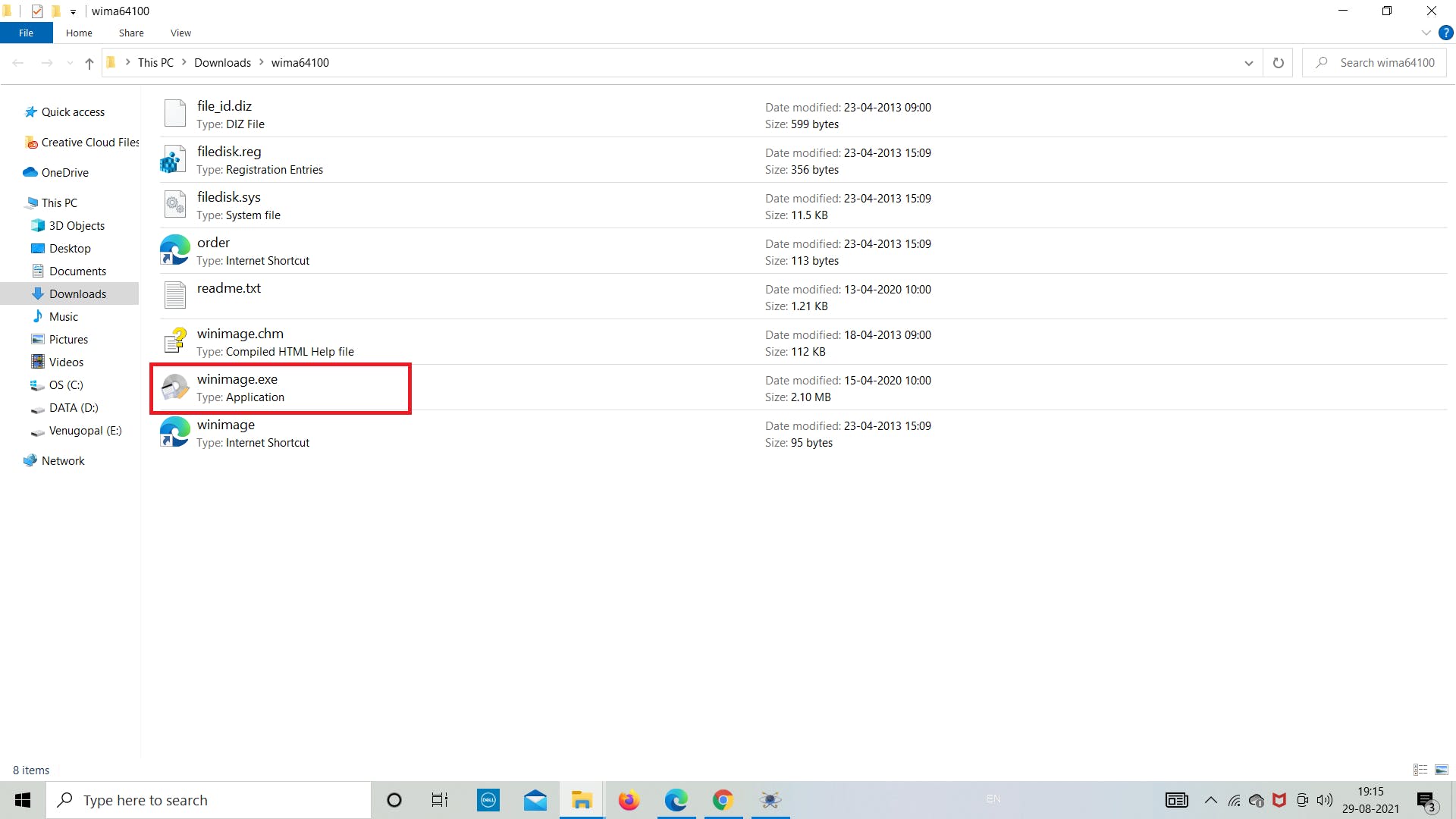
第 2 步:单击“确定”并继续 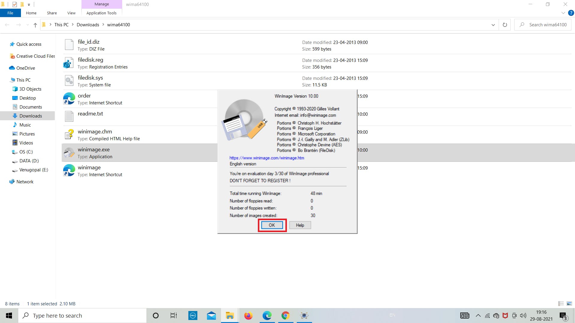
第 3 步:转到左上角的“文件” 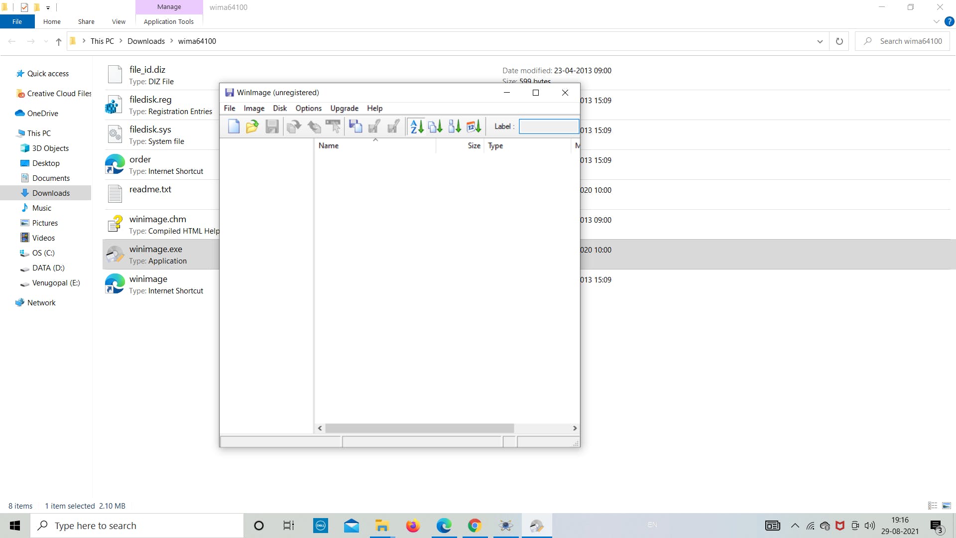
第四步:点击“新建” 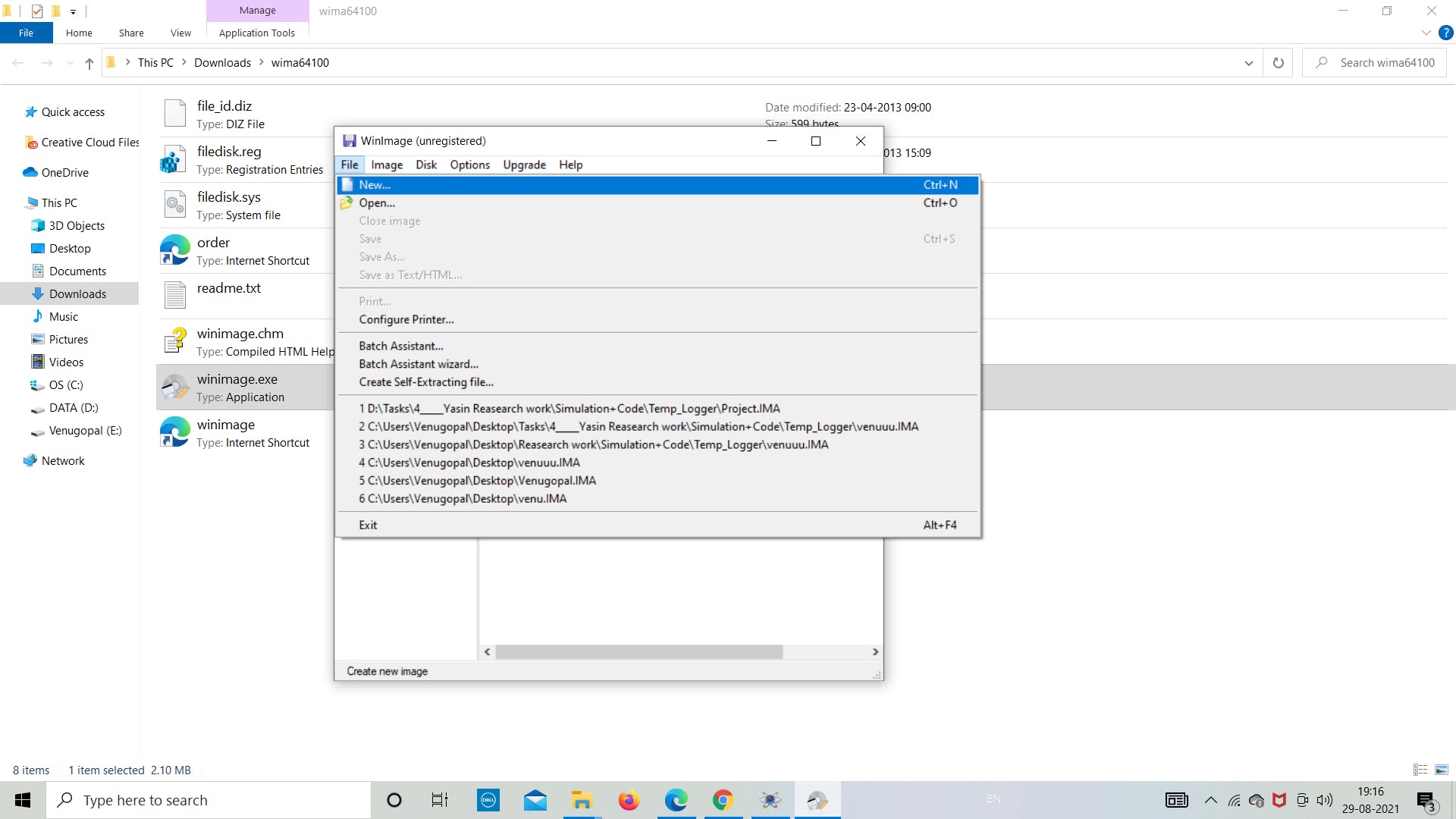
第 5 步:点击“选择自定义图像格式” 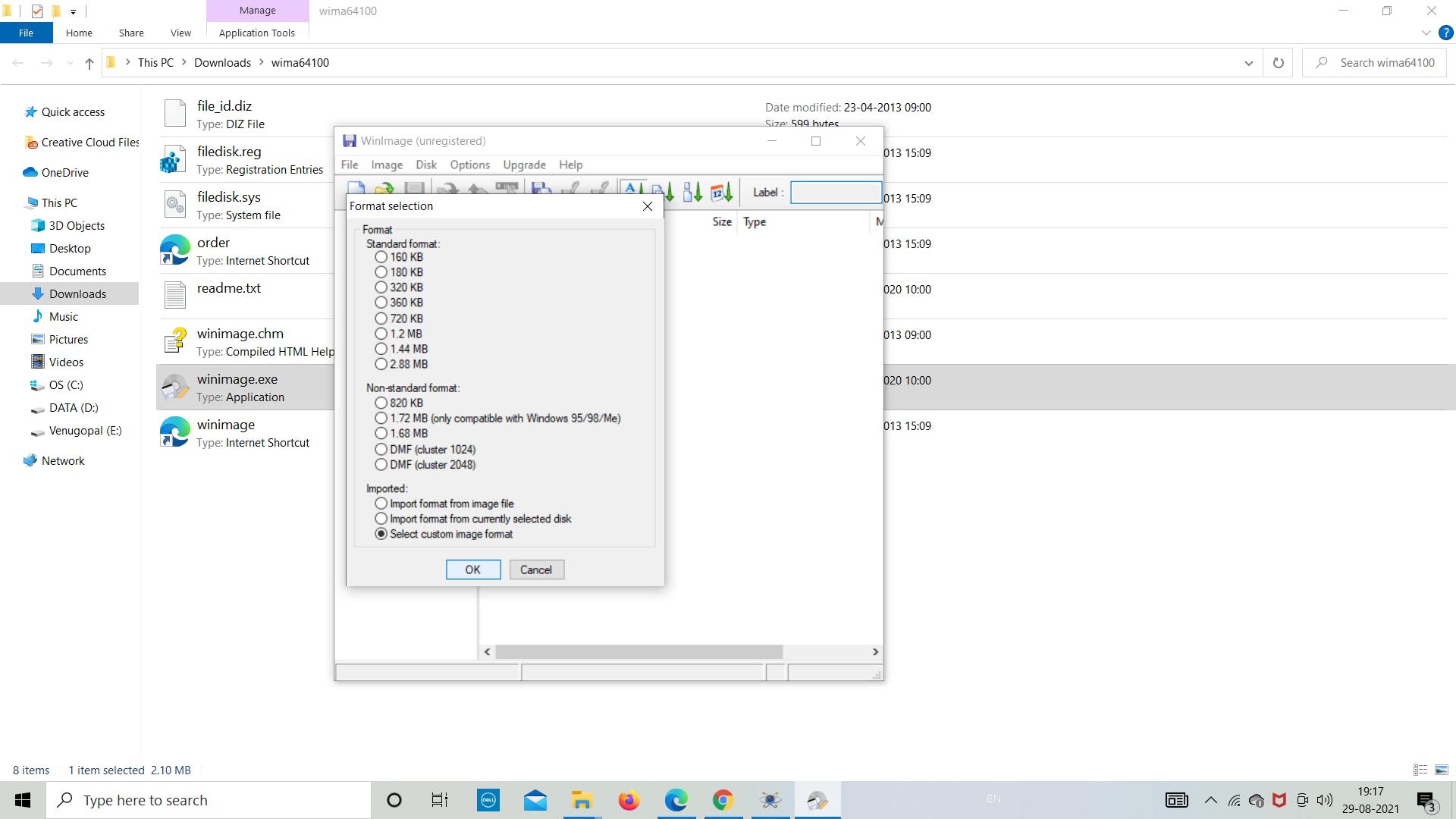
第 6 步:从下拉列表中选择“4 (2048)” 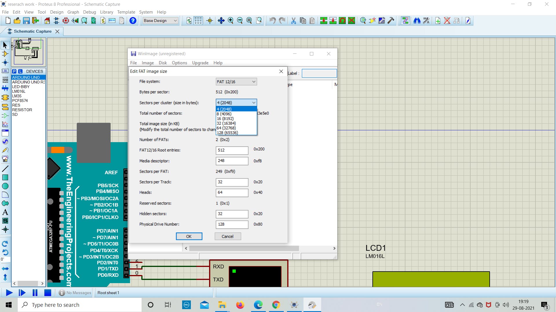
第7步:保持一切原样,然后单击“确定” 
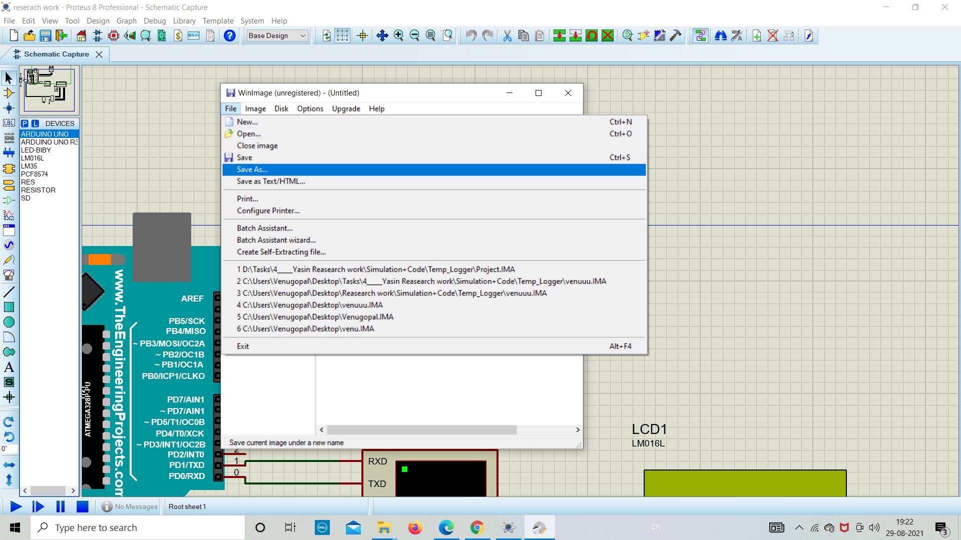
第8步:现在点击“文件”保存文件 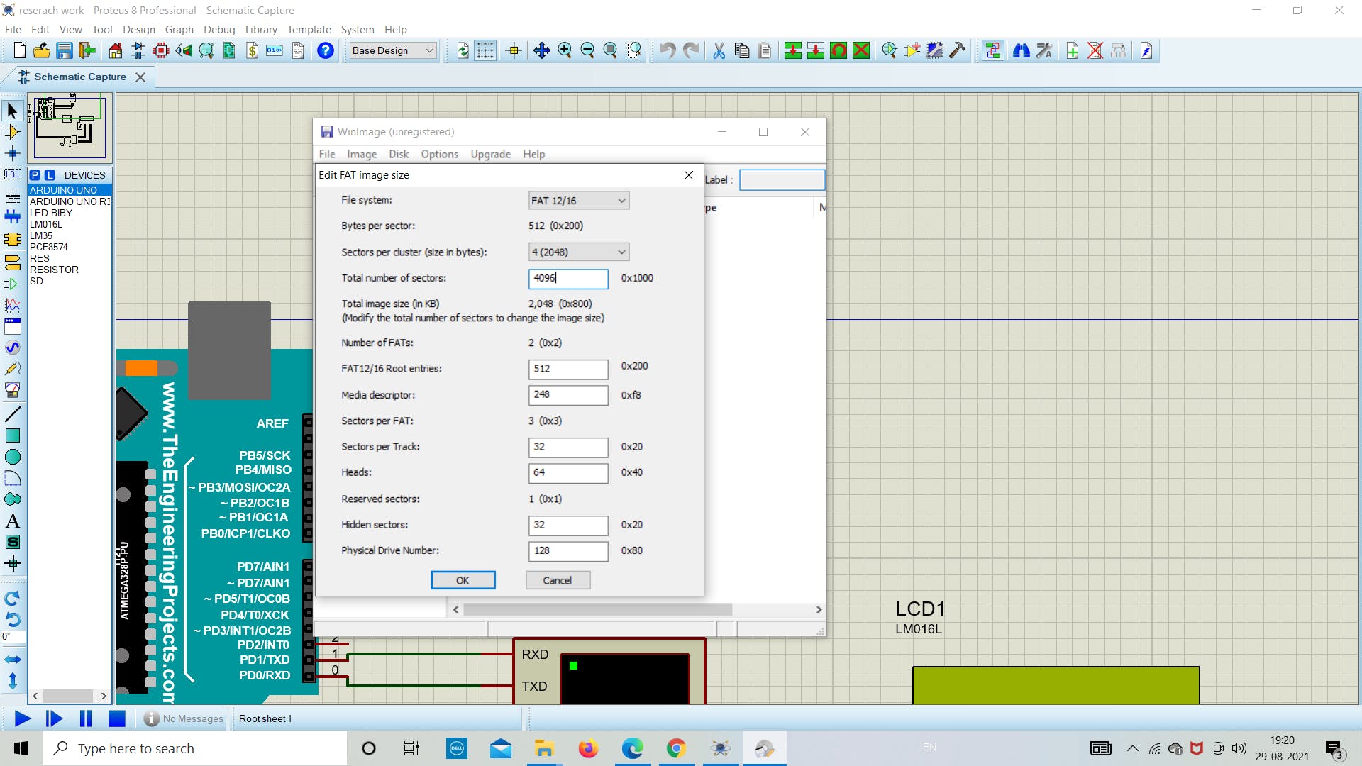
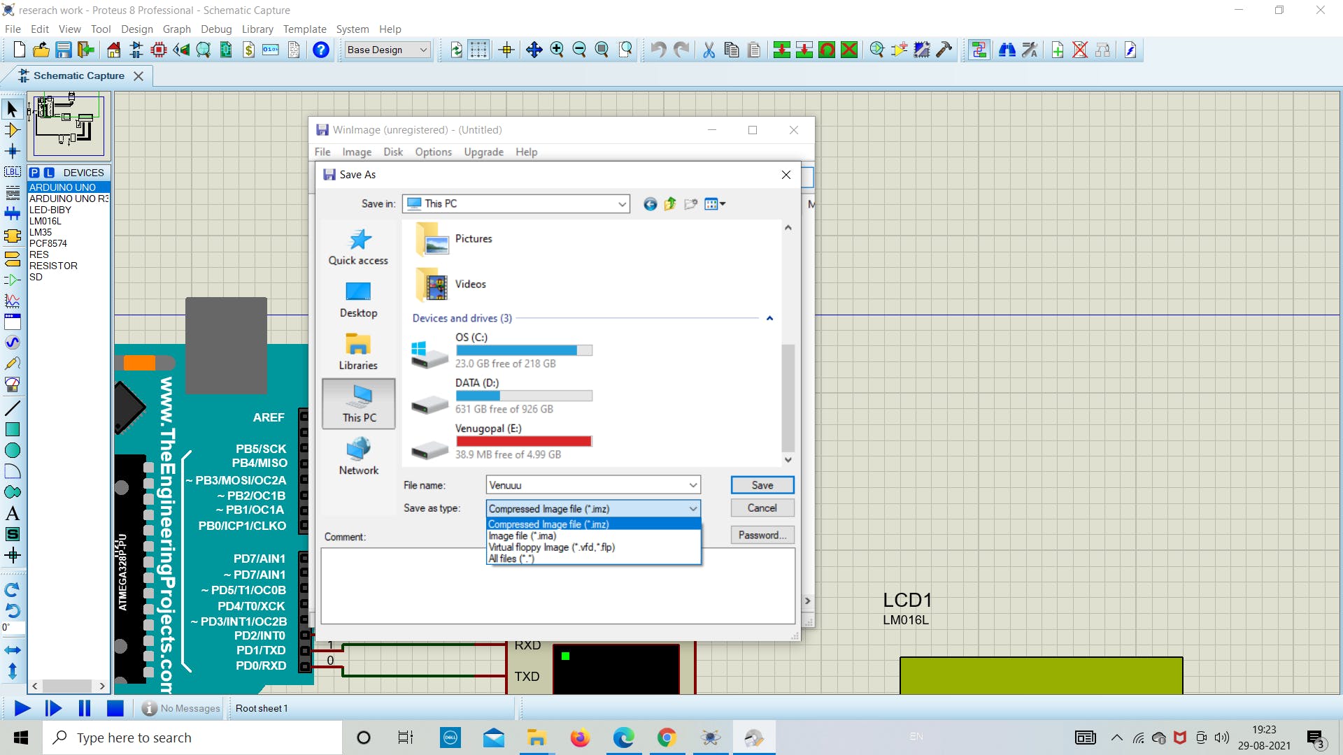
第 9 步:现在将文件“另存为”到目标文件夹 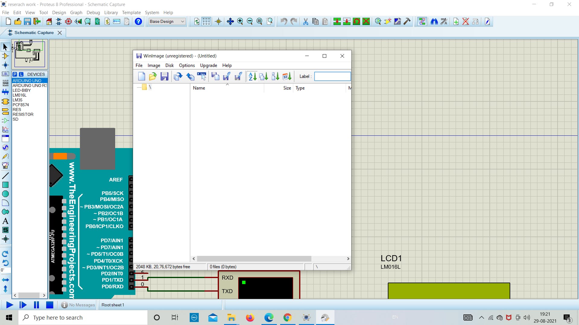
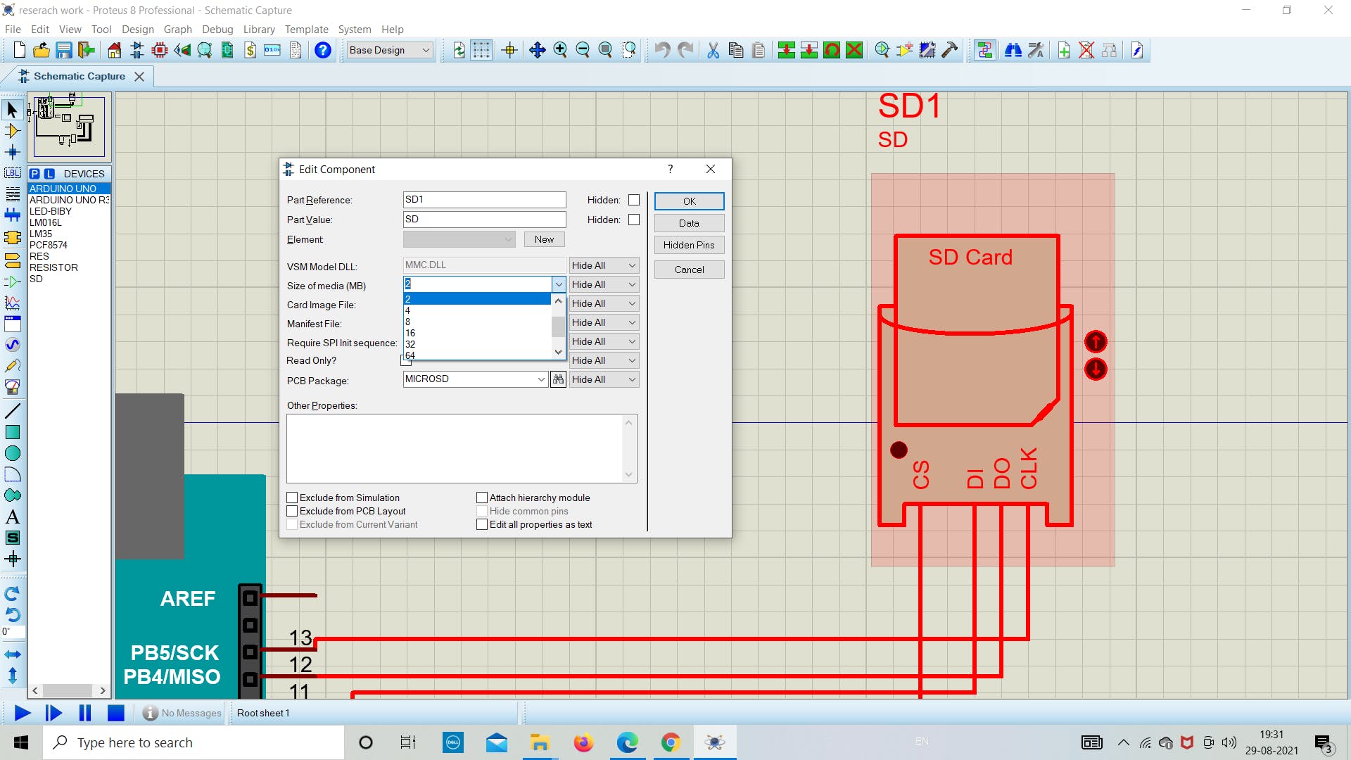
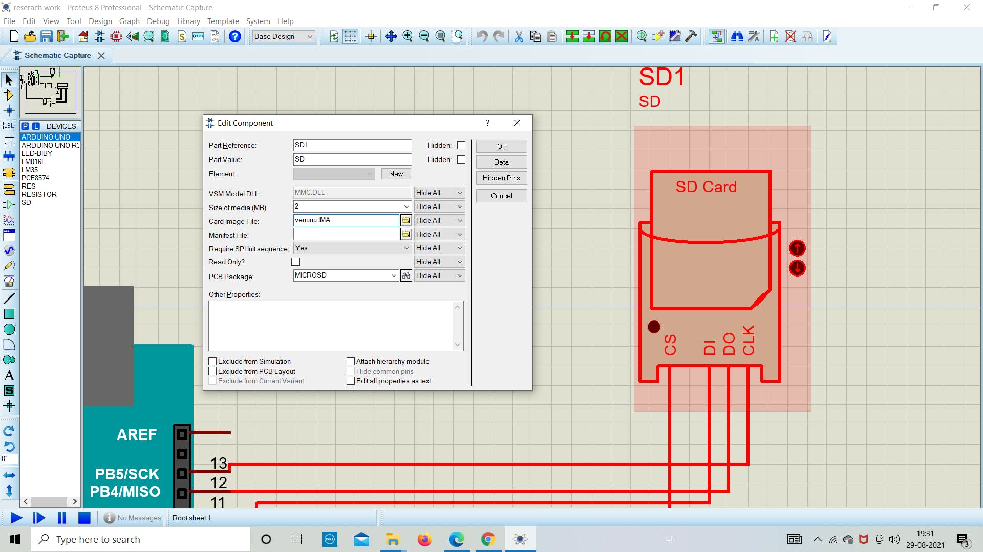
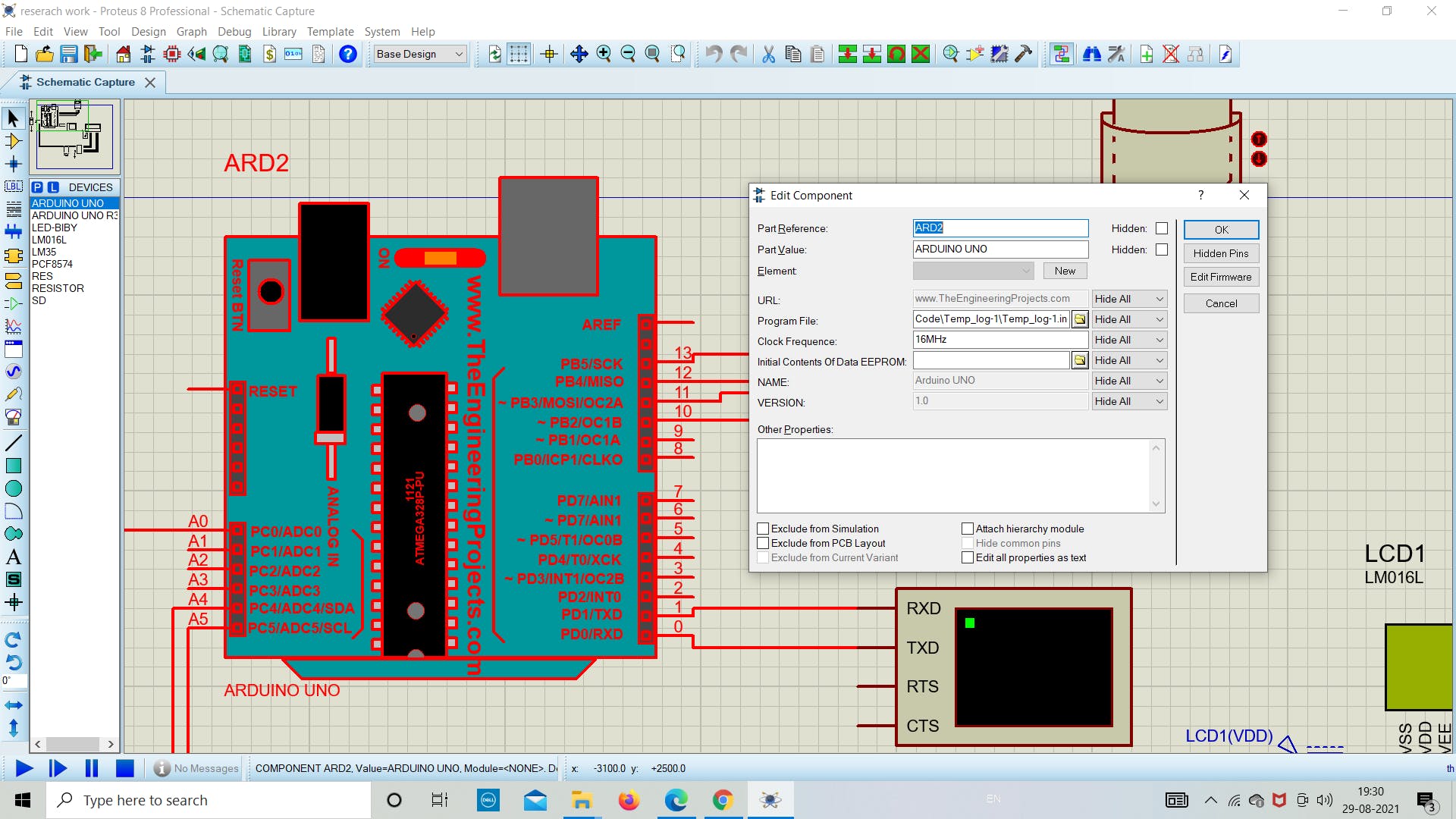
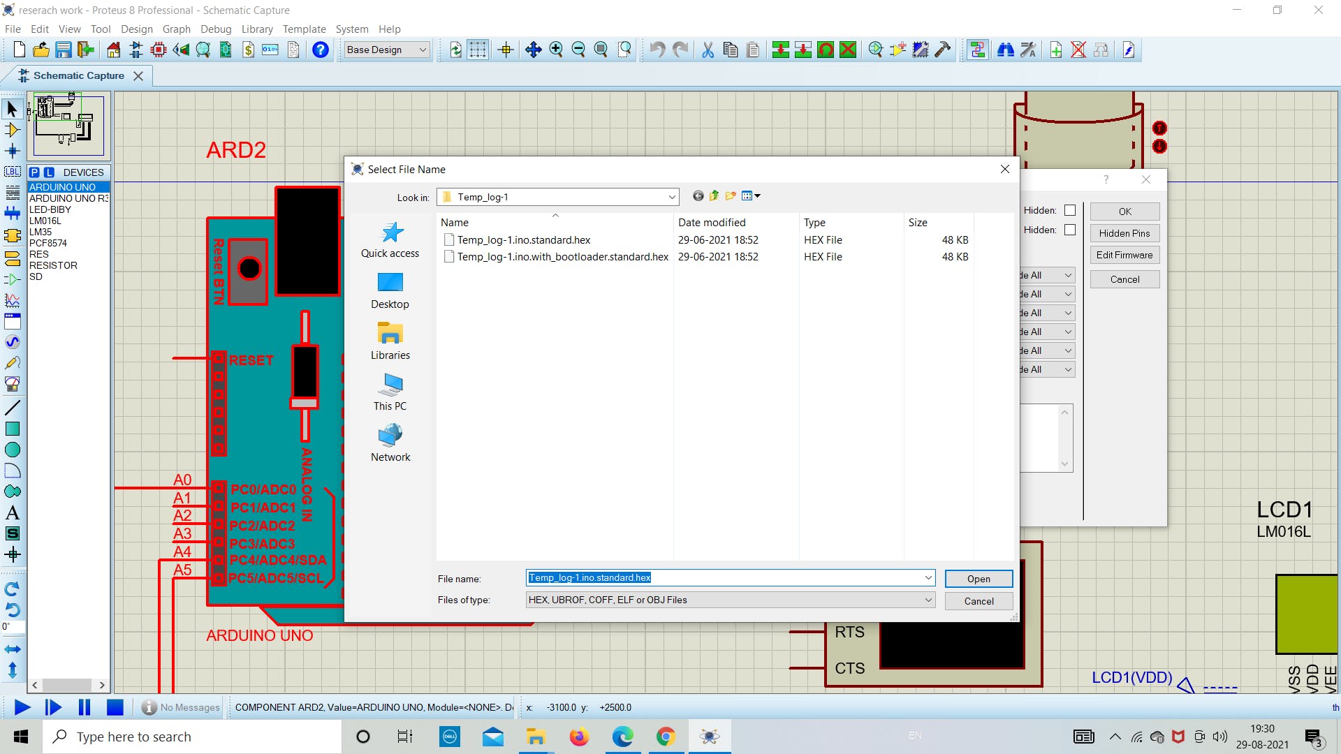
1. 模拟与编码 在成功设置了模拟所需的所有先决条件后,现在我们将深入研究在 proteus 中模拟 SD 卡模块的实际部分。现在在 proteus 中打开新文件,然后从软件列表中拖放所需的组件(参考下图),因为我们在上面提到了所有组件的名称。 在这里,我们使用 I2C (PCF8574) 将 LCD 连接到 Arduino,这允许使用较少数量的板上引脚。 在下一部分中,如下图所示分配 SD 卡模块中图像文件的文件路径,并选择文件大小为 2 MB。 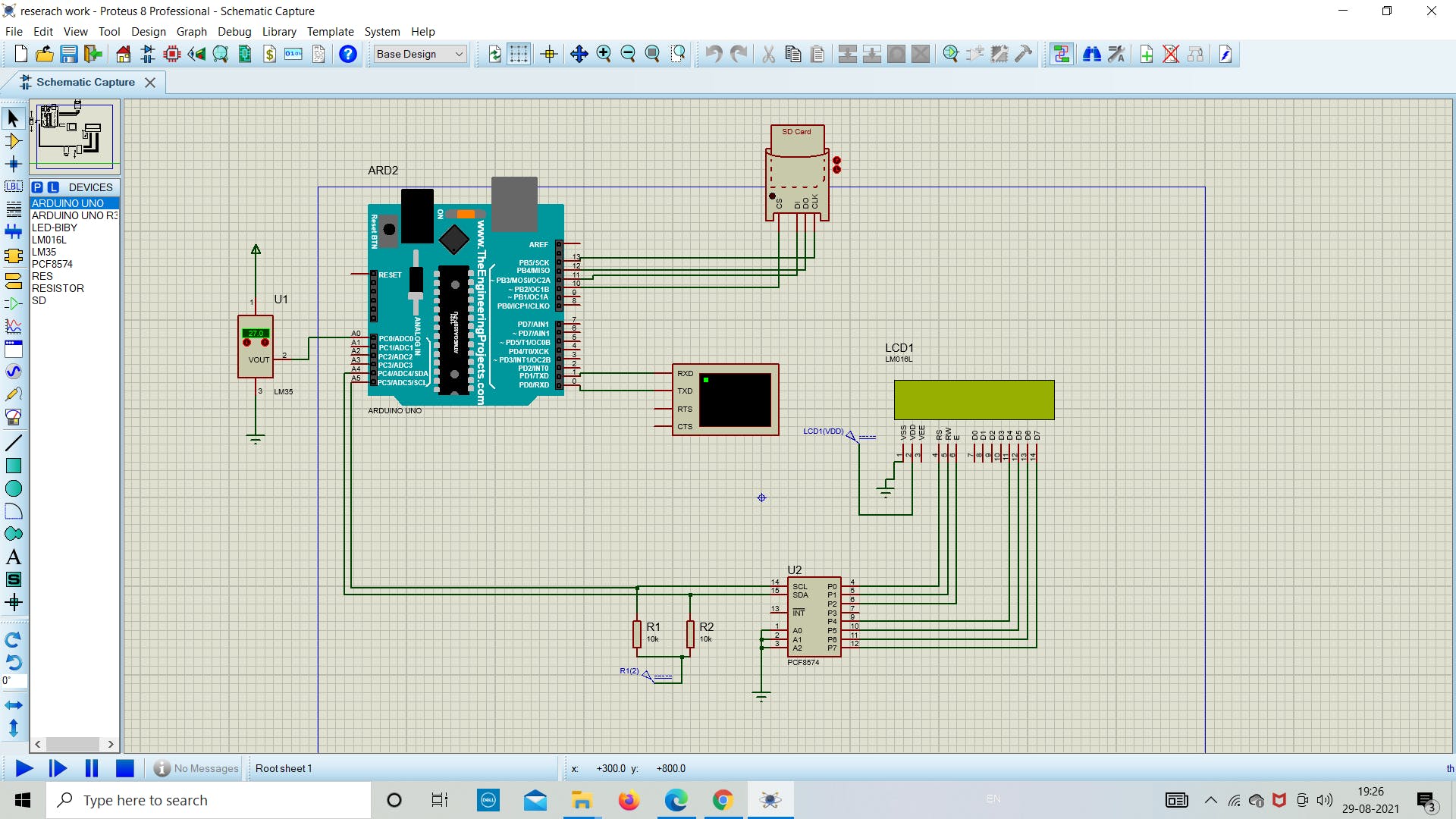
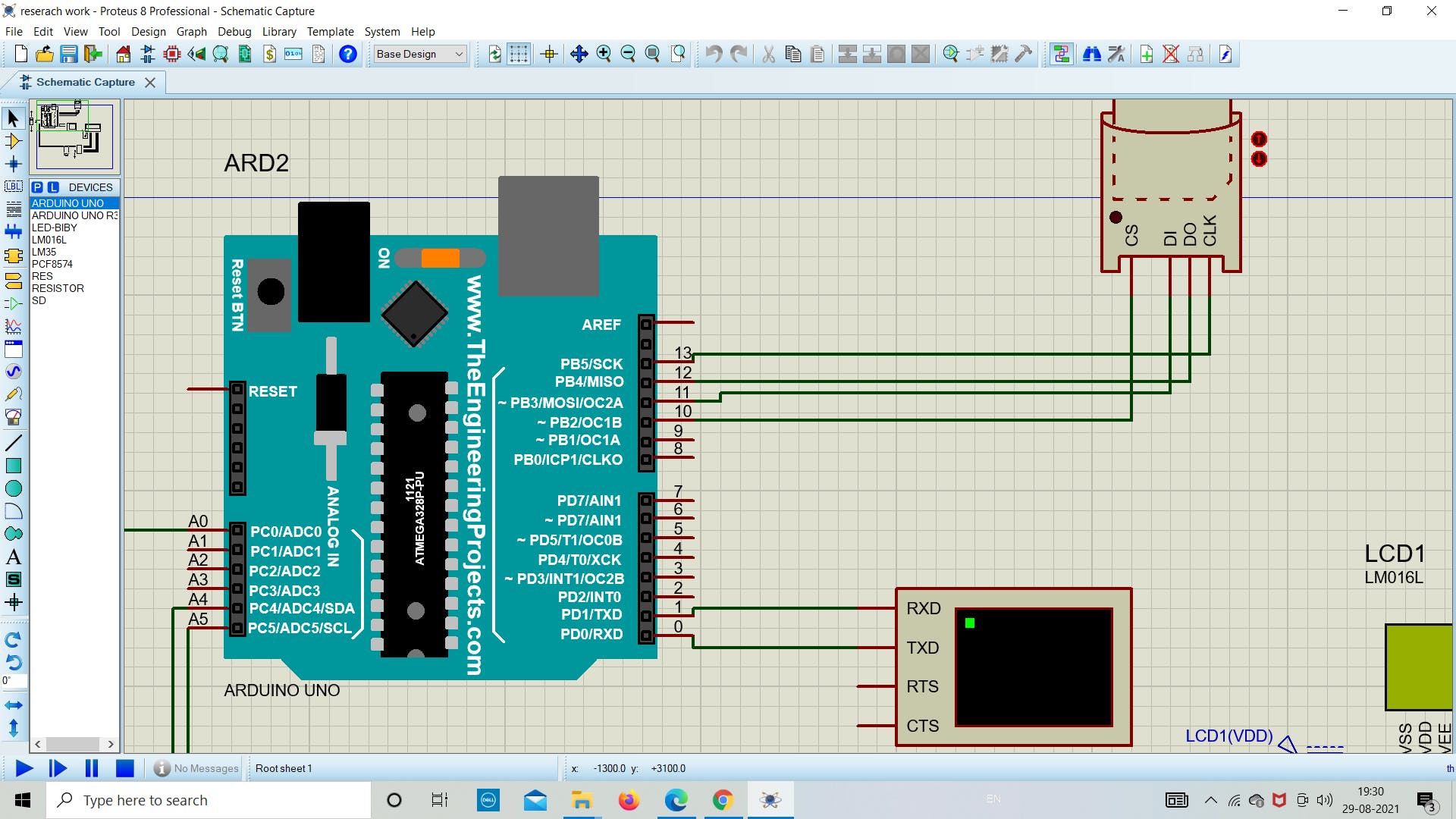
在这个阶段,我们将在 proteus 模拟中的 SD 卡模块中设置卡映像文件路径(下图相同)。 注意:请选择与您创建的图像文件相同的媒体大小(MB)。您可以根据需要创建任何大小的图像文件。 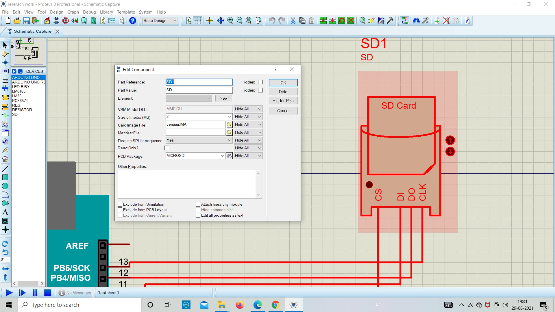
2. 检查 SD 卡的状态 现在我们在 Arduino 中添加下面的草图来了解 SD 卡模块的状态。 下面的草图用于了解我们的 SD 卡是否正确连接到 Arduino。如果没有找出原因并调试它。 上传下面的草图作为成功运行模拟的主要步骤。如果一切顺利,如下图所示,那么您就在正确的轨道上获得最终结果。 // Interfacing Arduino with SD card example (get SD card info) // include the SD library: #include #include // set up variables using the SD utility library functions: Sd2Card card; SdVolume volume; SdFile root; void setup() { // Open serial communications and wait for port to open: Serial.begin(9600); while (!Serial) { ; // wait for serial port to connect. Needed for native USB port only } Serial.print("\nInitializing SD card..."); // we'll use the initialization code from the utility libraries // since we're just testing if the card is working! if (!card.init()) { Serial.println("initialization failed. Things to check:"); Serial.println("* is a card inserted?"); Serial.println("* is your wiring correct?"); Serial.println("* did you change the chipSelect pin to match your shield or module?"); while (1); } else { Serial.println("Wiring is correct and a card is present."); } // print the type of card Serial.println(); Serial.print("Card type: "); switch (card.type()) { case SD_CARD_TYPE_SD1: Serial.println("SD1"); break; case SD_CARD_TYPE_SD2: Serial.println("SD2"); break; case SD_CARD_TYPE_SDHC: Serial.println("SDHC"); break; default: Serial.println("Unknown"); } // Now we will try to open the 'volume'/'partition' - it should be FAT16 or FAT32 if (!volume.init(card)) { Serial.println("Could not find FAT16/FAT32 partition.\nMake sure you've formatted the card"); while (1); } Serial.print("Clusters: "); Serial.println(volume.clusterCount()); Serial.print("Blocks x Cluster: "); Serial.println(volume.blocksPerCluster()); Serial.print("Total Blocks: "); Serial.println(volume.blocksPerCluster() * volume.clusterCount()); Serial.println(); // print the type and size of the first FAT-type volume uint32_t volumesize; Serial.print("Volume type is: FAT"); Serial.println(volume.fatType(), DEC); volumesize = volume.blocksPerCluster(); // clusters are collections of blocks volumesize *= volume.clusterCount(); // we'll have a lot of clusters volumesize /= 2; // SD card blocks are always 512 bytes (2 blocks are 1KB) Serial.print("Volume size (Kb): "); Serial.println(volumesize); Serial.print("Volume size (Mb): "); volumesize /= 1024; Serial.println(volumesize); Serial.print("Volume size (Gb): "); Serial.println((float)volumesize / 1024.0); Serial.println("\nFiles found on the card (name, date and size in bytes): "); root.openRoot(volume); // list all files in the card with date and size root.ls(LS_R | LS_DATE | LS_SIZE); } void loop(void) { }
3. 串行监视器输出 一旦我们在 Arduino 中上传程序,我们将在串行监视器中看到以下任何状态。 1.如果没有卡或Arduino无法连接到它,串口监视器将显示以下消息: 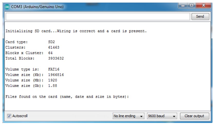
2.如果我们用 FAT16 文件系统放置一个 2 MB 的图像文件,我得到的结果如下所示: 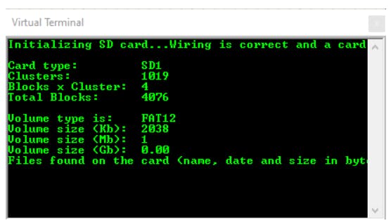 4. 编程、上传和存储
现在我们将生成代码并将其上传到 Arduino,以从 LM35 传感器获取温度值。带有日期和时间的温度值使用 winimage 存储在 .txt 文件中。我们在这里使用 LCD 为用户显示温度,而无需每次打开图像中的 .txt 文件。 将程序保存在所需位置并上传。作为参考,请使用下面的代码了解更多信息。 上传后运行模拟并等待一段时间在 SD 卡中存储 10-20 个读数。 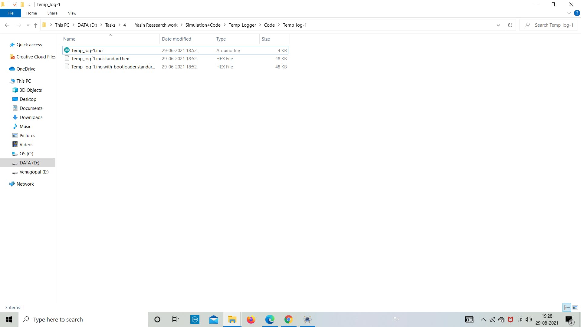
以下是要上传到 Arduino 板的最终草图。参考以下代码并将其保存在目标文件夹中。 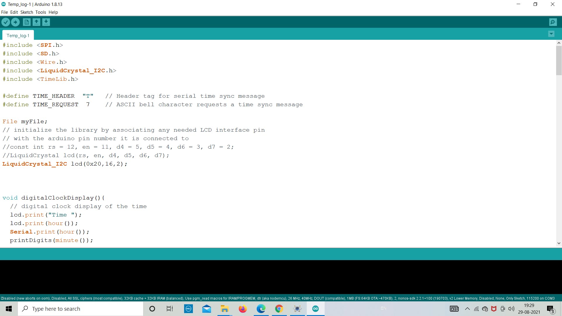
#include #include #include #include #include #define TIME_HEADER "T" // Header tag for serial time sync message #define TIME_REQUEST 7 // ASCII bell character requests a time sync message File myFile; // initialize the library by associating any needed LCD interface pin // with the arduino pin number it is connected to //const int rs = 12, en = 11, d4 = 5, d5 = 4, d6 = 3, d7 = 2; //LiquidCrystal lcd(rs, en, d4, d5, d6, d7); LiquidCrystal_I2C lcd(0x20,16,2); void digitalClockDisplay(){ // digital clock display of the time lcd.print("Time "); lcd.print(hour()); Serial.print(hour()); printDigits(minute()); printDigits(second()); lcd.setCursor(0, 1); lcd.print("Date "); lcd.print(day()); lcd.print("/"); lcd.print(month()); lcd.print("/"); lcd.print(year()); Serial.print(" "); Serial.print(day()); Serial.print(" "); Serial.print(month()); Serial.print(" "); Serial.print(year()); Serial.println(); } int printDigits(int digits){ // utility function for digital clock display: prints preceding colon and leading 0 lcd.print(":"); if(digits 10) lcd.print('0'); lcd.print(digits); return digits; } void processSyncMessage() { unsigned long pctime; const unsigned long DEFAULT_TIME = 1357041600; // Jan 1 2013 if(Serial.find(TIME_HEADER)) { pctime = Serial.parseInt(); if( pctime >= DEFAULT_TIME) { // check the integer is a valid time (greater than Jan 1 2013) setTime(pctime); // Sync Arduino clock to the time received on the serial port } } } time_t requestSync() { Serial.write(TIME_REQUEST); return 0; // the time will be sent later in response to serial mesg } void setup() { lcd.init(); lcd.init(); lcd.backlight(); Serial.begin(9600); // set up the LCD's number of columns and rows: if (!SD.begin(10)) { Serial.println("initialization failed!"); return; } else{ Serial.println("initialization Success!"); } myFile = SD.open("group.txt", FILE_WRITE); // if the file opened okay, write to it: if (myFile) { myFile.print("Date"); myFile.print(","); myFile.print("Time"); myFile.print(","); myFile.println("Temperature"); // close the file: myFile.close(); } else { Serial.print("error"); } while (!Serial) ; // Needed for Leonardo only pinMode(13, OUTPUT); setSyncProvider( requestSync); //set function to call when sync required Serial.println("Waiting for sync message"); lcd.print("Loading....."); lcd.clear(); } void loop() { if (Serial.available()) { processSyncMessage(); } if (timeStatus()!= timeNotSet) { digitalClockDisplay(); } if (timeStatus() == timeSet) { digitalWrite(13, HIGH); // LED on if synced } else { digitalWrite(13, LOW); // LED off if needs refresh } int lm35_pin = A0; float temperature = analogRead(lm35_pin); temperature = (temperature*500)/1023; File data_file = SD.open("group.txt", FILE_WRITE); if (data_file) { data_file.print(day()); data_file.print("/"); data_file.print(month()); data_file.print("/"); data_file.print(year()); data_file.print(","); data_file.print(hour()); data_file.print(":"); // Serial.print(hour()); int p= printDigits(minute()); data_file.print(p); data_file.print(":"); int m= printDigits(second()); data_file.print(m); data_file.print(","); data_file.println(temperature); data_file.close(); } else { Serial.print("error"); } delay(800); lcd.setCursor(0, 0); }
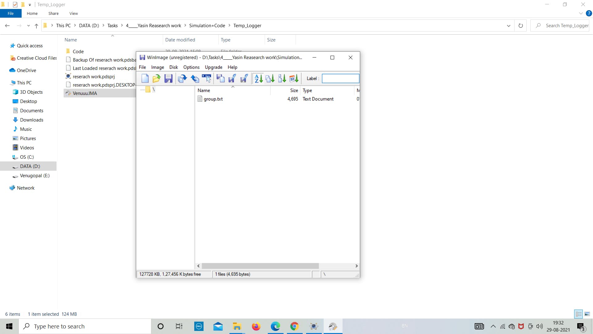
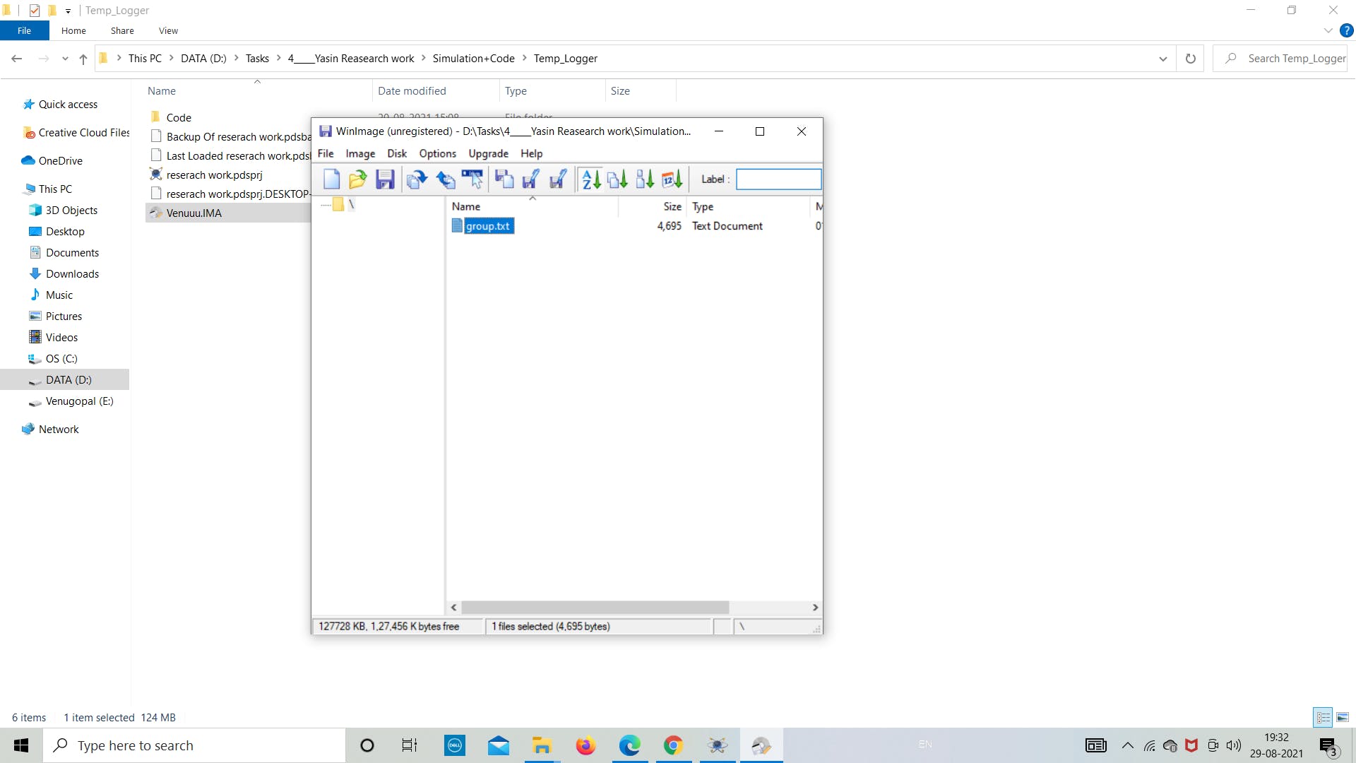
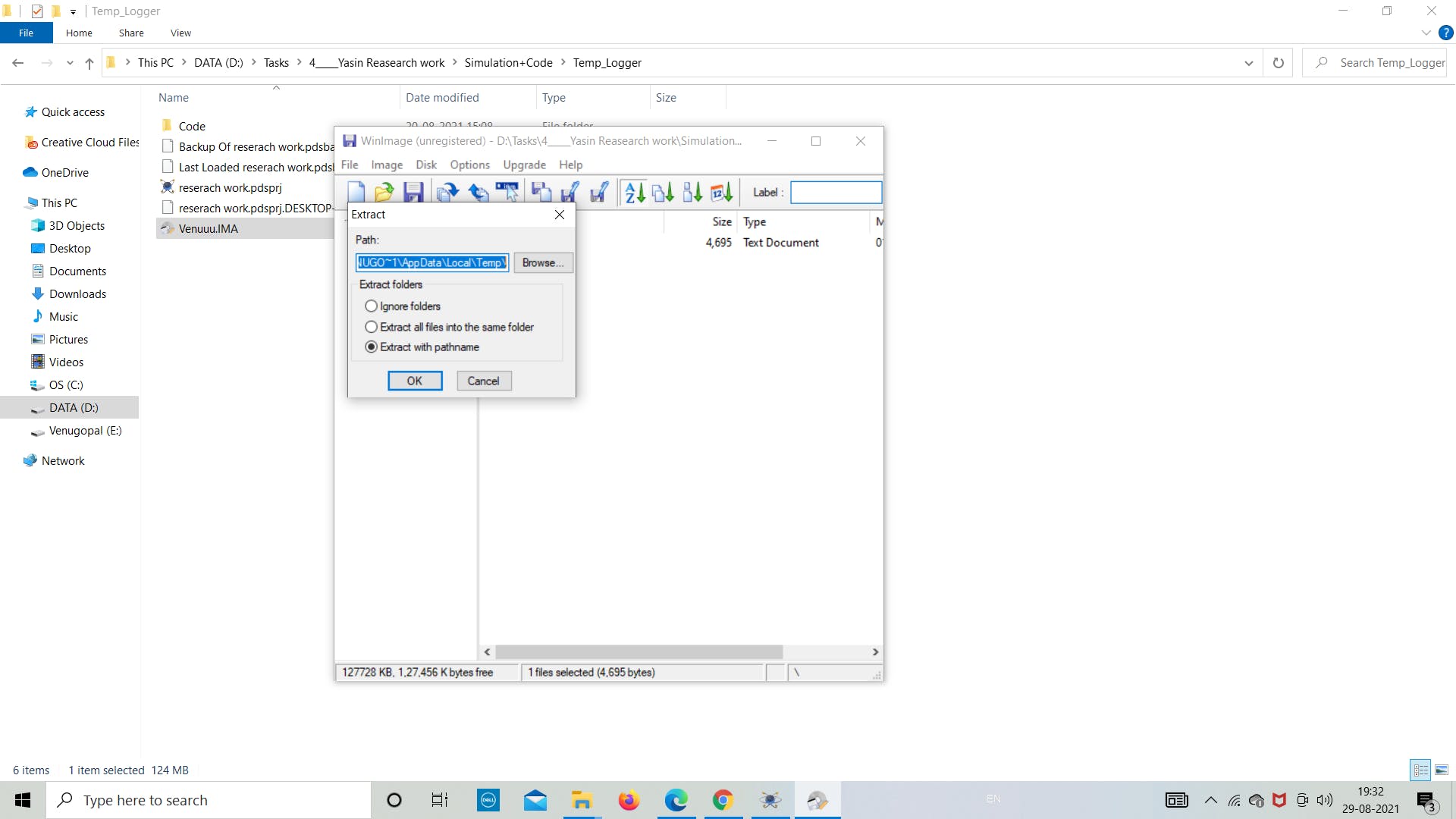
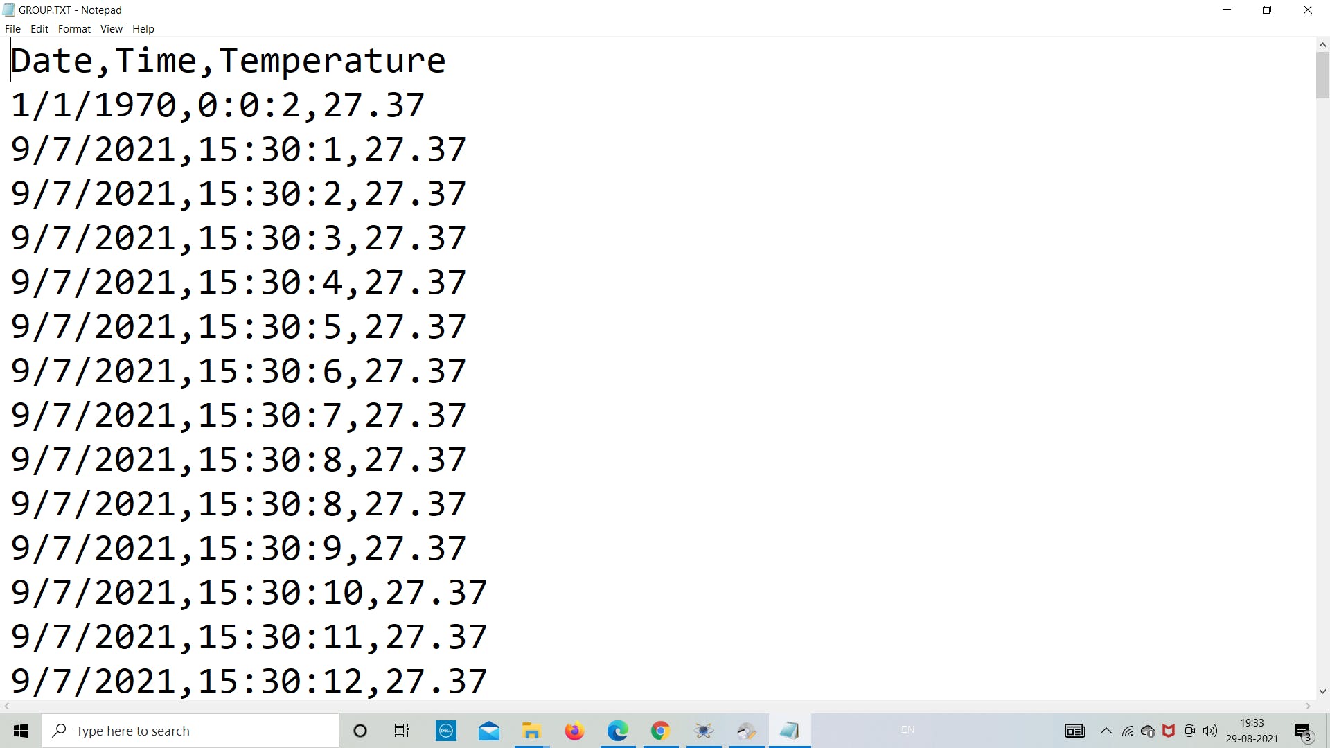
5. 导出 SD 卡数据 正如我们在模拟部分所做的那样,现在让我们看看数据是否存储在图像文件中。 让我们打开“Venuuu.IMG”文件来查看图像文件中的内容。 如下图所示,我们可以看到在图像文件中创建了名为“group.txt”的.txt文件。现在我们将通过双击它来导出文件。然后它会自动打开文件,我们可以看到里面存储的温度数据。 按照下图重新创建实验。 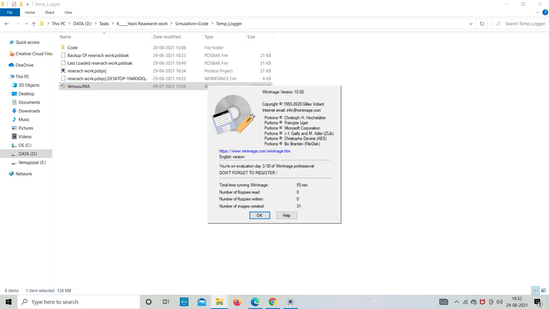
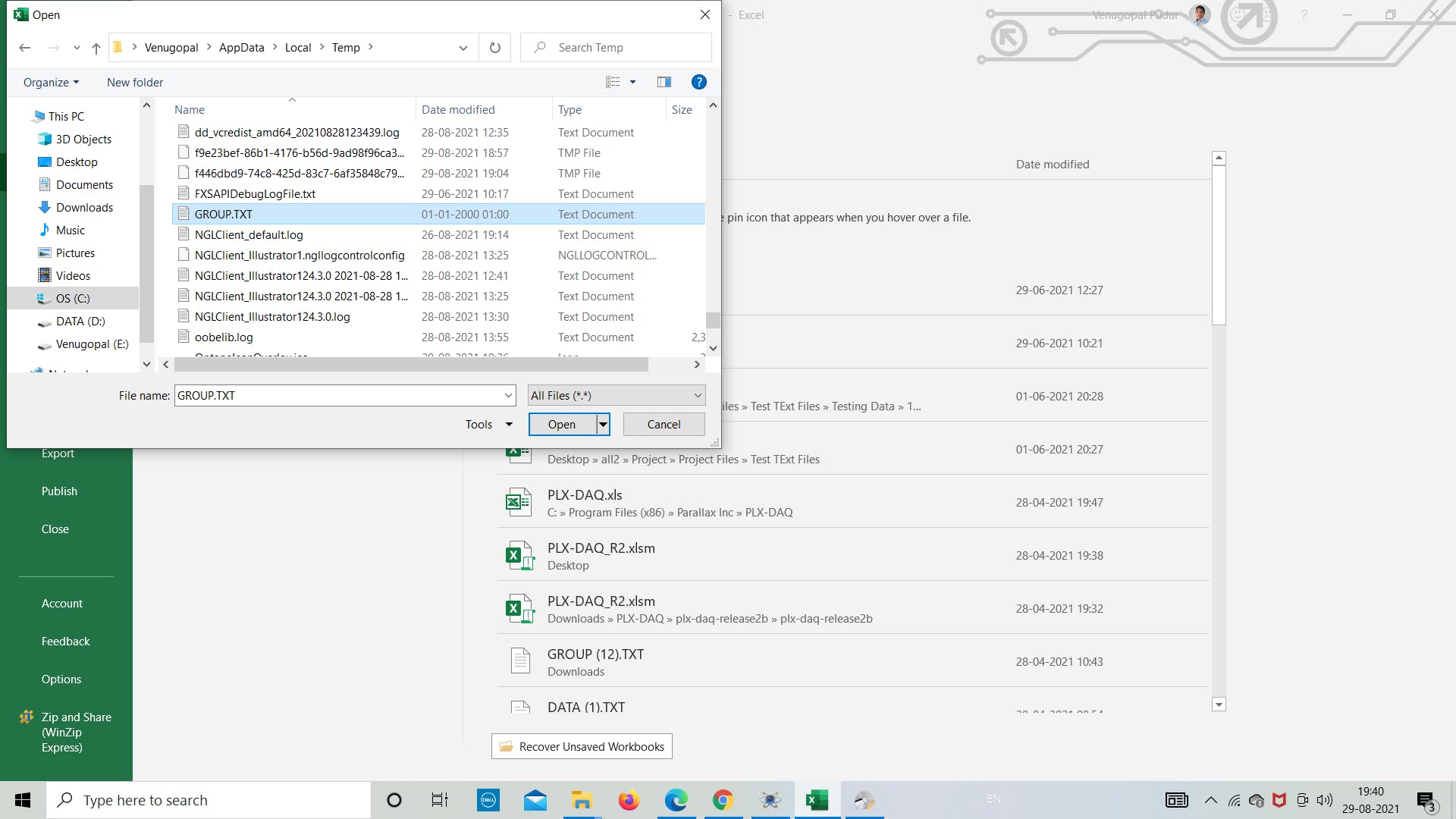
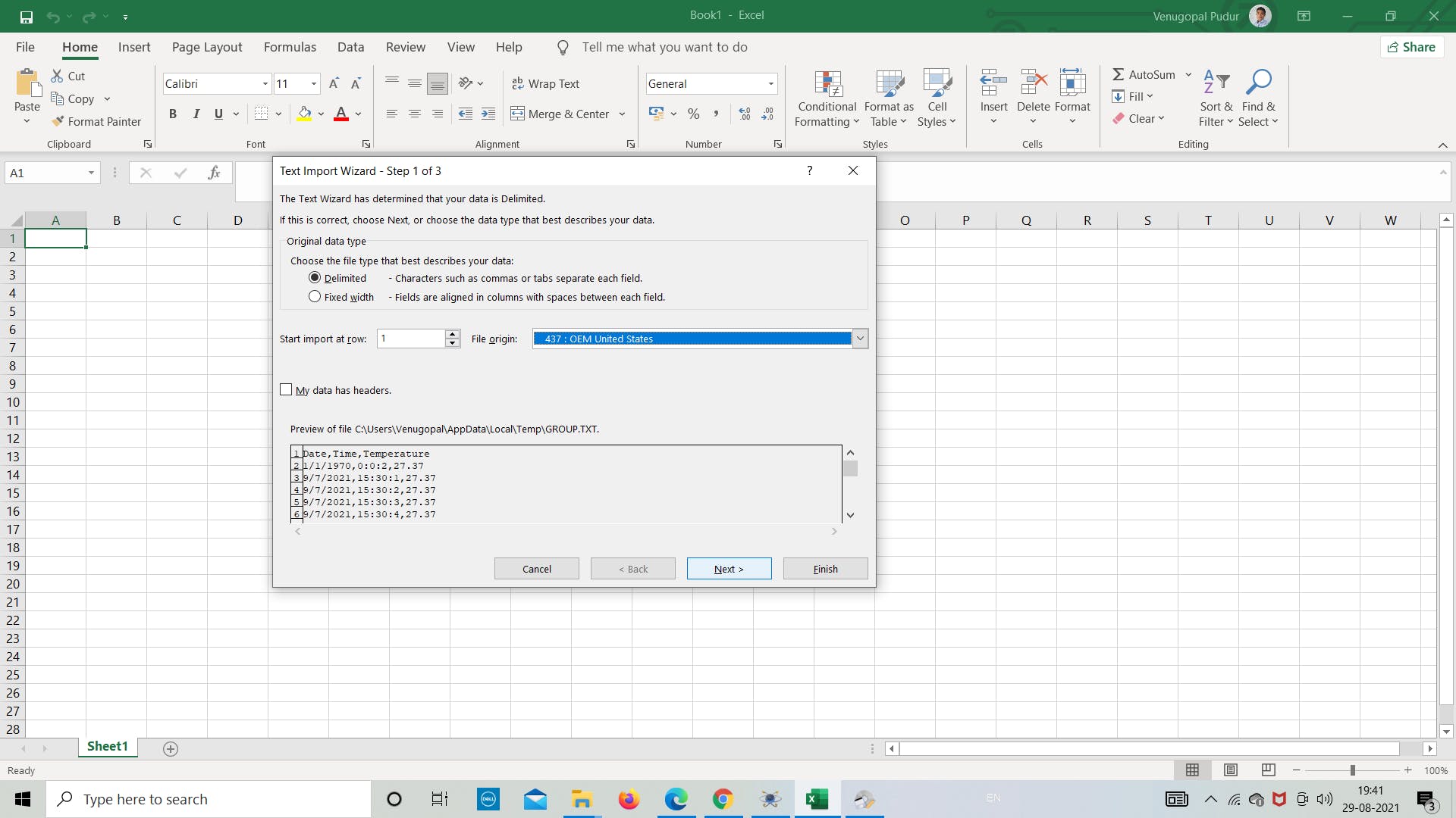
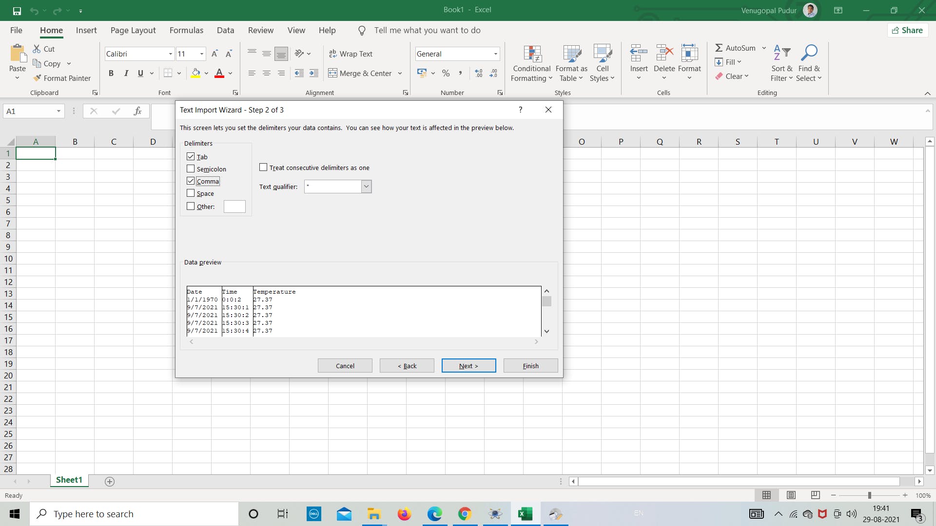
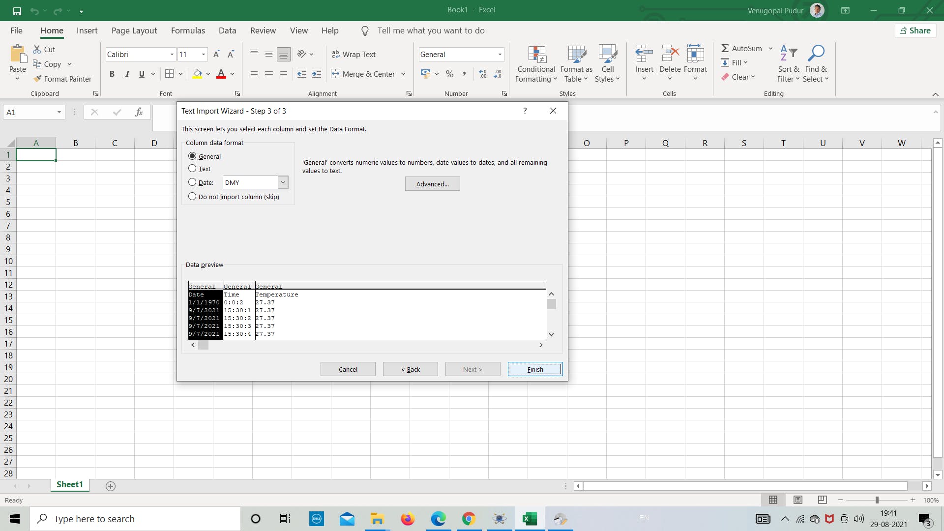
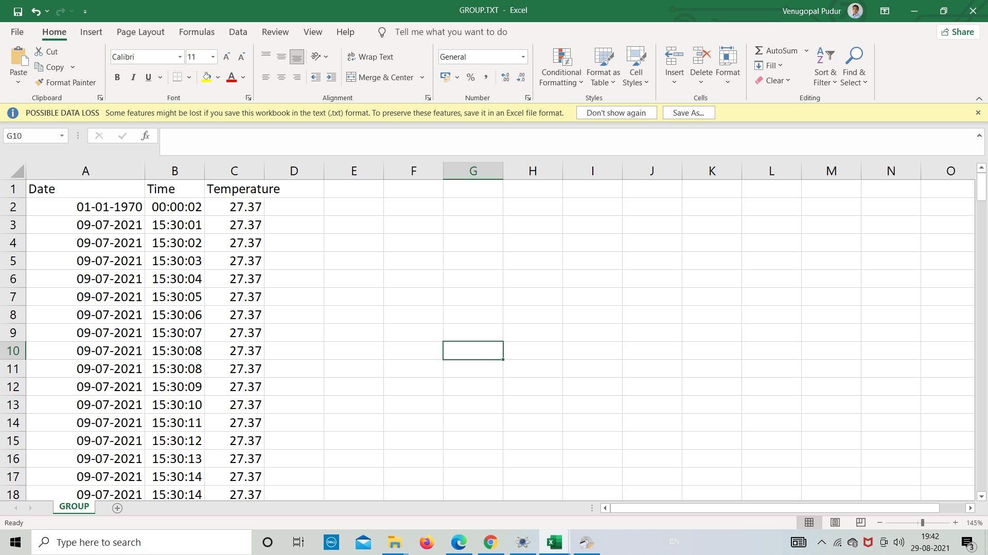
现在我们打开 excel 将文件转换为 excel 格式,以便根据数据或任何其他我们想要的目的绘制图形。 打开 .txt 文件并将分隔符设置为用逗号分隔以将数据分隔为列,然后根据需要继续分析数据。
这都是关于使用 SD 卡模块在 Proteus 中进行的简单模拟。 感谢您阅读本文,祝您有美好的一天! |
【本文地址】