|
3D 模型渲染
模型(Model)Primitives 简单的模型复杂的模型模型的组成几何纹理图片材质模型及描述
模型文件格式
什么叫渲染渲染管线顶点着色(顶点处理)片段着色(片段处理)
UE4 模型渲染UE4程序化模型渲染UProceduralMeshComponentUStaticMeshComponentUPrimitiveComponent&UMeshComponent
参考
模型(Model)
 这里只着重三角形网格Mesh模型(三角形化)。 这里只着重三角形网格Mesh模型(三角形化)。
Primitives 简单的模型
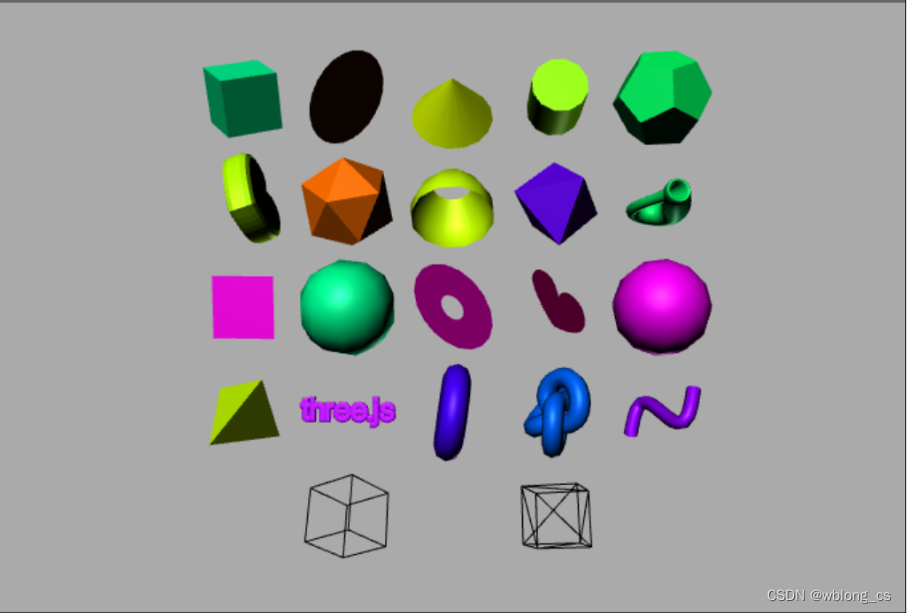
复杂的模型
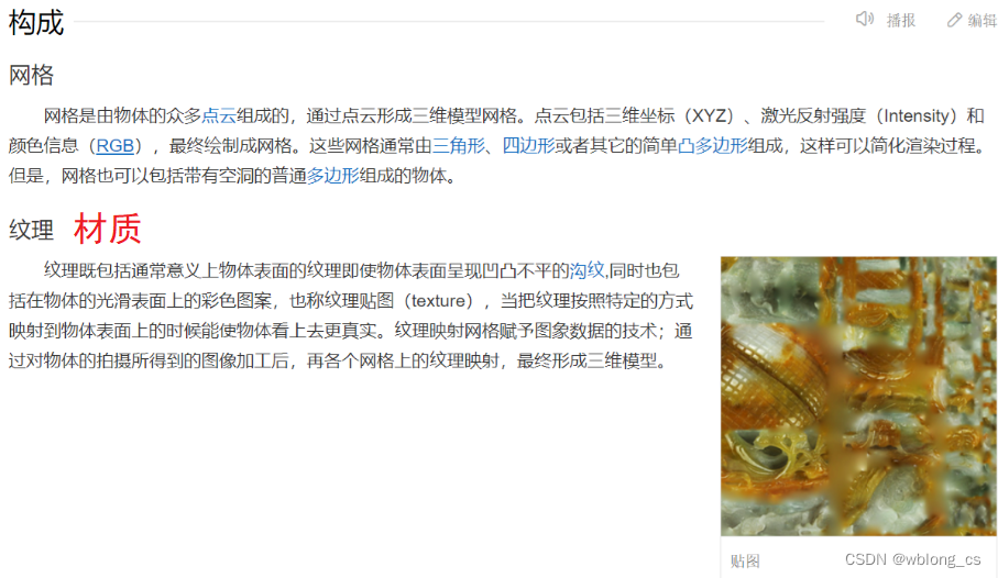
模型的组成
几何
例如最简单的obj格式的模型文件存储的内容:
v 几何体顶点(Geometric vertices)vt 贴图坐标(Texture vertices)vn 顶点法线(Vertex normals)f (三角)面索引(Face) 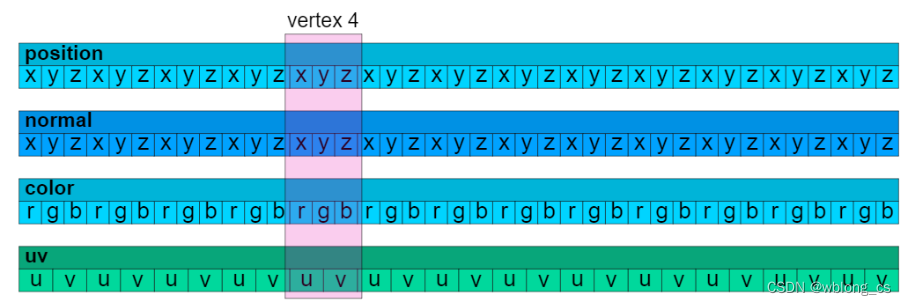 纹理图片
纹理图片
常见的图片格式JPG、PNG、BMP等等。 
材质模型及描述
MeshBasicMaterial(贴图或本身颜色MeshLambertMaterial(基于顶点)MeshPhongMaterial (基于像素)MeshStandardMaterial (粗糙度和金属度)MeshPhysicalMaterial 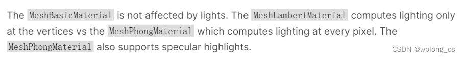 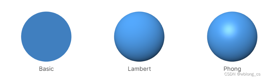 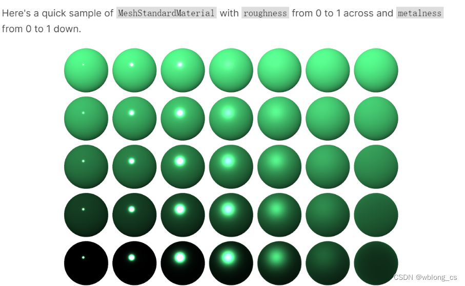 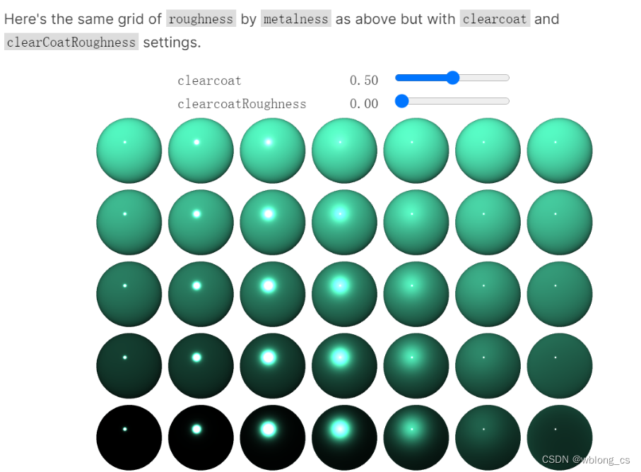  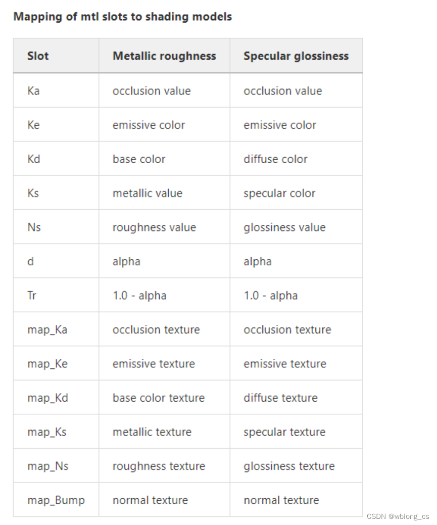 模型文件格式
模型的格式有很多中,如obj、gltf、stl、fbx、3dmax、OSGB、3DTiles、Revit及IFC等等,除了以上最基本的数据外,还保存了其他诸如场景关系、属性数据、拓扑数据及动画骨骼数据等等。
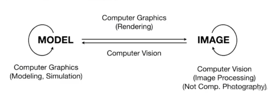
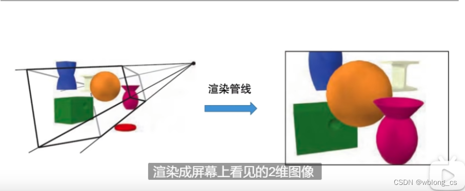
什么叫渲染
简单来说就是用Image来表达Model,即几何数据(3D&2D Model)的可视化展现。
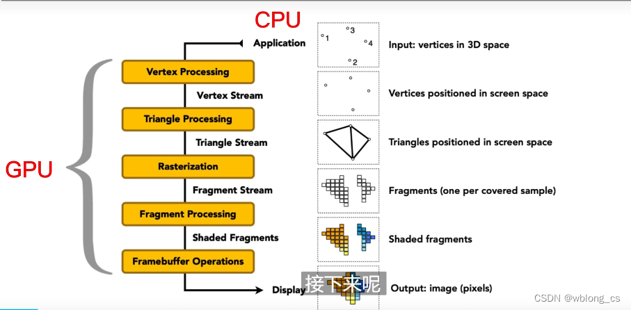
渲染管线
  这里主要说明两点顶点着色和片段着色。 这里主要说明两点顶点着色和片段着色。 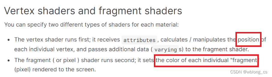
顶点着色(顶点处理)
一个顶点着色器的工作是生成裁剪空间坐标值。 模型中几何顶点数据大都是以局部坐标存储的,即模型的中心点在模型上或是附近。将模型渲染到屏幕上需要进行的一系列坐标转换(Transform)。 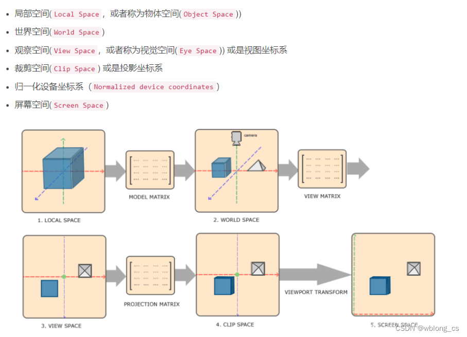 UE4 封装的相关函数: UE4 封装的相关函数:
void FSceneView::DeprojectScreenToWorld(const FVector2D& ScreenPos, const FIntRect& ViewRect, const FMatrix& InvViewProjMatrix, FVector& out_WorldOrigin, FVector& out_WorldDirection)
{
float PixelX = FMath::TruncToFloat(ScreenPos.X);
float PixelY = FMath::TruncToFloat(ScreenPos.Y);
// Get the eye position and direction of the mouse cursor in two stages (inverse transform projection, then inverse transform view).
// This avoids the numerical instability that occurs when a view matrix with large translation is composed with a projection matrix
// Get the pixel coordinates into 0..1 normalized coordinates within the constrained view rectangle
const float NormalizedX = (PixelX - ViewRect.Min.X) / ((float)ViewRect.Width());
const float NormalizedY = (PixelY - ViewRect.Min.Y) / ((float)ViewRect.Height());
// Get the pixel coordinates into -1..1 projection space
const float ScreenSpaceX = (NormalizedX - 0.5f) * 2.0f;
const float ScreenSpaceY = ((1.0f - NormalizedY) - 0.5f) * 2.0f;
// The start of the ray trace is defined to be at mousex,mousey,1 in projection space (z=1 is near, z=0 is far - this gives us better precision)
// To get the direction of the ray trace we need to use any z between the near and the far plane, so let's use (mousex, mousey, 0.5)
const FVector4 RayStartProjectionSpace = FVector4(ScreenSpaceX, ScreenSpaceY, 1.0f, 1.0f);
const FVector4 RayEndProjectionSpace = FVector4(ScreenSpaceX, ScreenSpaceY, 0.5f, 1.0f);
// Projection (changing the W coordinate) is not handled by the FMatrix transforms that work with vectors, so multiplications
// by the projection matrix should use homogeneous coordinates (i.e. FPlane).
const FVector4 HGRayStartWorldSpace = InvViewProjMatrix.TransformFVector4(RayStartProjectionSpace);
const FVector4 HGRayEndWorldSpace = InvViewProjMatrix.TransformFVector4(RayEndProjectionSpace);
FVector RayStartWorldSpace(HGRayStartWorldSpace.X, HGRayStartWorldSpace.Y, HGRayStartWorldSpace.Z);
FVector RayEndWorldSpace(HGRayEndWorldSpace.X, HGRayEndWorldSpace.Y, HGRayEndWorldSpace.Z);
// divide vectors by W to undo any projection and get the 3-space coordinate
if (HGRayStartWorldSpace.W != 0.0f)
{
RayStartWorldSpace /= HGRayStartWorldSpace.W;
}
if (HGRayEndWorldSpace.W != 0.0f)
{
RayEndWorldSpace /= HGRayEndWorldSpace.W;
}
const FVector RayDirWorldSpace = (RayEndWorldSpace - RayStartWorldSpace).GetSafeNormal();
// Finally, store the results in the outputs
out_WorldOrigin = RayStartWorldSpace;
out_WorldDirection = RayDirWorldSpace;
}
bool FSceneView::ProjectWorldToScreen(const FVector& WorldPosition, const FIntRect& ViewRect, const FMatrix& ViewProjectionMatrix, FVector2D& out_ScreenPos)
{
FPlane Result = ViewProjectionMatrix.TransformFVector4(FVector4(WorldPosition, 1.f));
if ( Result.W > 0.0f )
{
// the result of this will be x and y coords in -1..1 projection space
const float RHW = 1.0f / Result.W;
FPlane PosInScreenSpace = FPlane(Result.X * RHW, Result.Y * RHW, Result.Z * RHW, Result.W);
// Move from projection space to normalized 0..1 UI space
const float NormalizedX = ( PosInScreenSpace.X / 2.f ) + 0.5f;
const float NormalizedY = 1.f - ( PosInScreenSpace.Y / 2.f ) - 0.5f;
FVector2D RayStartViewRectSpace(
( NormalizedX * (float)ViewRect.Width() ),
( NormalizedY * (float)ViewRect.Height() )
);
out_ScreenPos = RayStartViewRectSpace + FVector2D(static_cast(ViewRect.Min.X), static_cast(ViewRect.Min.Y));
return true;
}
return false;
}
片段着色(片段处理)
一个片段着色器的工作是为当前光栅化的像素提供颜色值。 每一个片段(像素)的color值,由你所选的“材质”决定,光照的影响及本身特性(颜色)组合。 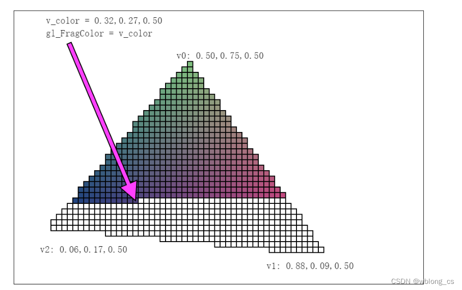
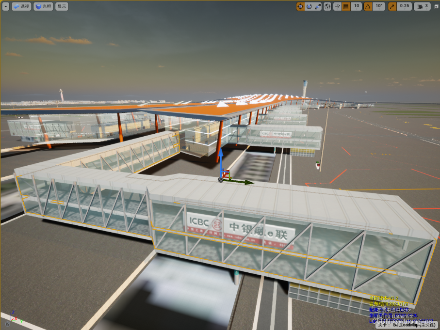
UE4 模型渲染
UE4 引擎提供了强大的编辑器(场景编辑器、材质编辑器及蓝图编辑器等等),大大简化三维渲染的复杂性。
场景编辑器:模型的拖动、缩放和旋转,简单操作就可以实现局部坐标到世界坐标的转换。材质编辑器:不用考虑复杂的顶点着色和片段着色器代码的编写(HLSL)。蓝图编辑器:不用写C++代码,就可以完成一些游戏逻辑。
UE4程序化模型渲染
在UE4开发中, 通常用到的Mesh有StaticMesh,SkeletalMesh,ProceduralMesh等等, 它们对应都有相应的渲染组件如UStaticMeshComponent, UProceduralMeshComponent, 本质上这些Mesh组件都继承了UPrimitiveComponent, UPrimitiveComponent通过FPrimitiveSceneProxy渲染代理负责将特定的Mesh的渲染数据(VertexBuffer, IndexBuffer, Material)从游戏线程送往渲染线程。有时候为了定制某种特殊的Mesh渲染, 我们得自定义新的PrimitiveComponent。(当然UProceduralMeshComponent往往满足了定制新的Mesh需求, 但有时候为了进一步的性能或者进行特殊的MeshPass得定制PrimitiveComponent)。
UE4中涉及Mesh Model的组件:

UProceduralMeshComponent
UProceduralMeshComponent* meshComp =NewObject(this, meshName);
meshComp->RegisterComponent();
meshComp->AttachToComponent(RootComponent,
UTexture2D* texture = GetTextrue2D(meshInfo->mImageResolutionS, meshInfo->mImageResolutionT, meshInfo->mImageSize, meshInfo->mImageData, meshInfo->mTextureFormat);
TArray normals; //法线
TArray tangents;
TArray vertexColors; //顶点颜色
meshComp->CreateMeshSection_LinearColor(0, meshInfo->mVerticeArray, meshInfo->mTriangleArray, normals,
meshInfo->mTexCoordArray, vertexColors, tangents, true);
if (materialTemp != nullptr)
{
UMaterialInstanceDynamic* dynamicMaterial = UMaterialInstanceDynamic::Create(materialTemp, this);
dynamicMaterial->SetTextureParameterValue("PagedLodTex", texture);
meshComp->SetMaterial(0, dynamicMaterial);
}
UStaticMeshComponent
参考cesium for unreal 相关代码 CesiumForUnreal\Source\CesiumRuntime\Private\CesiumGltfComponent.cpp
UPrimitiveComponent&UMeshComponent
参考电缆Mesh的实现:Engine\Plugins\Runtime\CableComponent\Source\CableComponent\Classes\CableComponent.h 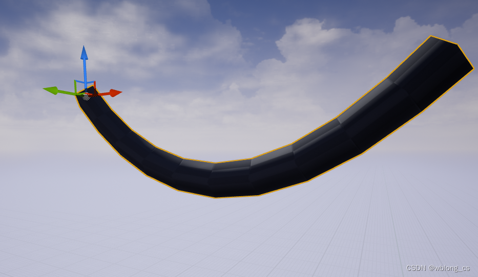
参考
1、https://www.bilibili.com/video/BV1X7411F744/?spm_id_from=333.999.0.0&vd_source=378fcf68e20d55ad4334c47f1ce0a8f7
2、https://www.bilibili.com/video/BV1sN4y1A7Xv/?spm_id_from=333.1007.top_right_bar_window_history.content.click&vd_source=378fcf68e20d55ad4334c47f1ce0a8f7
|