stm32 si5351使用(软件模拟i2c和硬件i2c) |
您所在的位置:网站首页 › stm32频率发生器 › stm32 si5351使用(软件模拟i2c和硬件i2c) |
stm32 si5351使用(软件模拟i2c和硬件i2c)
|
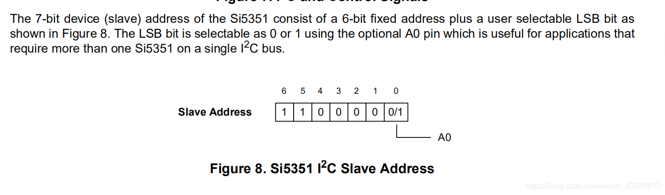
参考资料来源 csdn: Si5351A方波信号发生器发送任意频率程序. github: SI5351时钟模块测试代码. 使用的单片机为STM32F030 i2c引脚为PB8(SCL),PB9(SDA) 需要记住的地方有: si5351设备地址:写地址0xC0,读地址为0xC1(手册的第四章可以看到)si5351的寄存器和输出频率的计算要看另一本手册 下载: AN619.
先说下软件模拟的i2c,这个好测试,因为万一别人画的板引脚反了改一下就可以测试了(惨痛教训)。 i2c.c #include "i2c.h" // 初始化IIC的IO口 void I2C2_Soft_Init(void) { GPIO_InitTypeDef GPIO_InitStructure; // 定义GPIO结构体 RCC_AHBPeriphClockCmd(RCC_AHBPeriph_GPIOB, ENABLE); // 打开GPIOB口时钟 GPIO_InitStructure.GPIO_Mode = GPIO_Mode_OUT; // 输出 GPIO_InitStructure.GPIO_OType = GPIO_OType_OD; // 开漏 GPIO_InitStructure.GPIO_Pin = Pin_SCL | Pin_SDA ; // IIC对应IO口 GPIO_InitStructure.GPIO_PuPd = GPIO_PuPd_UP; // 上拉 GPIO_InitStructure.GPIO_Speed = GPIO_Speed_Level_3; // 50MHZ GPIO_Init(GPIOB, &GPIO_InitStructure); // 初始化GPIO I2C2_Stop(); } // 发送IIC起始信号 bool I2C2_Start(void) { Pin_SCL_H; // 拉高时钟线 Pin_SDA_H; // 拉高信号线 I2C2_Delay1us(); if(!Read_SDA_Pin) return false; Pin_SDA_L; I2C2_Delay1us(); Pin_SDA_L; I2C2_Delay1us(); return true; } // 发送IIC停止信号 bool I2C2_Stop(void) { Pin_SCL_H; Pin_SDA_L; I2C2_Delay1us(); if(Read_SDA_Pin) return false; Pin_SDA_H; I2C2_Delay1us(); if(!Read_SDA_Pin) return false; Pin_SDA_H; I2C2_Delay1us(); return true; } // IIC发送ACK信号 void I2C2_Ack(void) { Pin_SCL_L; I2C2_Delay1us(); Pin_SDA_L; Pin_SCL_H; I2C2_Delay1us(); Pin_SCL_L; Pin_SDA_H; I2C2_Delay1us(); } // IIC不发送ACK信号 void I2C2_NAck(void) { Pin_SCL_L; I2C2_Delay1us(); Pin_SDA_H; Pin_SCL_H; I2C2_Delay1us(); Pin_SCL_L; I2C2_Delay1us(); } // IIC等待ACK信号 uint8_t I2C2_Wait_Ack(void) { Pin_SCL_L; I2C2_Delay1us(); Pin_SDA_H; Pin_SCL_H; I2C2_Delay1us(); if(Read_SDA_Pin) { Pin_SCL_L; I2C2_Delay1us(); return false; } Pin_SCL_L; I2C2_Delay1us(); return true; } // IIC发送一个字节 void I2C2_Send_Byte(uint8_t txd) { for(uint8_t i=0; i uint8_t rxd = 0; for(uint8_t i=0; i rxd |= 0x01; } } return rxd; } // 向从机指定地址写数据 bool I2C_Write_REG(uint8_t SlaveAddress, uint8_t REG_Address,uint8_t REG_data) { if(!I2C2_Start()) return false; I2C2_Send_Byte(SlaveAddress); if(!I2C2_Wait_Ack()) { I2C2_Stop(); return false; } I2C2_Send_Byte(REG_Address); if(!I2C2_Wait_Ack()) { I2C2_Stop(); return false; } I2C2_Send_Byte(REG_data); if(!I2C2_Wait_Ack()) { I2C2_Stop(); return false; } if(!I2C2_Stop()) return false; return true; } // 从设备中读取数据 uint8_t I2C2_Read_REG(uint8_t SlaveAddress,uint8_t REG_Address) { uint8_t data; if(!I2C2_Start()) return false; I2C2_Send_Byte(SlaveAddress); if(!I2C2_Wait_Ack()) { I2C2_Stop(); return false; } I2C2_Send_Byte(REG_Address); if(!I2C2_Wait_Ack()) { I2C2_Stop(); return false; } if(!I2C2_Start()) return false; I2C2_Send_Byte(SlaveAddress + 1); if(!I2C2_Wait_Ack()) { I2C2_Stop(); return false; } data = I2C2_Read_Byte(); I2C2_NAck(); if(!I2C2_Stop()) return false; return data; } // 连续写N个字节 bool I2C2_Write_NByte(uint8_t SlaveAddress, uint8_t REG_Address, uint8_t* buf, uint8_t len) { if(!I2C2_Start())return false; I2C2_Send_Byte(SlaveAddress); //发送设备地址+写信号 if(!I2C2_Wait_Ack()){I2C2_Stop(); return false;} I2C2_Send_Byte(REG_Address); if(!I2C2_Wait_Ack()){I2C2_Stop(); return false;} for(uint16_t i=0; i if(!I2C2_Wait_Ack()){I2C2_Stop(); return false;} } } I2C2_Stop(); return true; } bool I2C2_CheckDevice(uint8_t SlaveAddress) { if(!I2C2_Start()) return false; I2C2_Send_Byte(SlaveAddress); if(!I2C2_Wait_Ack()) { I2C2_Stop(); return false; } if(!I2C2_Stop()) return false; return true; } bool my_I2C_sendREG(uint8_t REG_Address,uint8_t REG_data) { if(!I2C2_Start()) return false; I2C2_Send_Byte(0xC0); if(!I2C2_Wait_Ack()) { I2C2_Stop(); return false; } I2C2_Send_Byte(REG_Address); if(!I2C2_Wait_Ack()) { I2C2_Stop(); return false; } I2C2_Send_Byte(REG_data); if(!I2C2_Wait_Ack()) { I2C2_Stop(); return false; } if(!I2C2_Stop()) return false; return true; } uint8_t my_I2C2_Read_REG(uint8_t REG_Address) { uint8_t data; if(!I2C2_Start()) return false; I2C2_Send_Byte(0xC0); if(!I2C2_Wait_Ack()) { I2C2_Stop(); return false; } I2C2_Send_Byte(REG_Address); if(!I2C2_Wait_Ack()) { I2C2_Stop(); return false; } if(!I2C2_Start()) return false; I2C2_Send_Byte(0xC1); if(!I2C2_Wait_Ack()) { I2C2_Stop(); return false; } data = I2C2_Read_Byte(); I2C2_NAck(); if(!I2C2_Stop()) return false; return data; }i2c.h #ifndef __I2C_H #define __I2C_H #include "stm32f0xx.h" typedef unsigned short int uint; typedef enum {false = 0, true = !false} bool; #define I2C2_GPIOx GPIOB #define Pin_SCL GPIO_Pin_8//8 #define Pin_SDA GPIO_Pin_9//9 #define Pin_SCL_L I2C2_GPIOx->ODR &= ~Pin_SCL #define Pin_SCL_H I2C2_GPIOx->ODR |= Pin_SCL #define Pin_SDA_L I2C2_GPIOx->ODR &= ~Pin_SDA #define Pin_SDA_H I2C2_GPIOx->ODR |= Pin_SDA #define Read_SDA_Pin I2C2_GPIOx->IDR & Pin_SDA #define SI_CLK0_CONTROL 16 // Register definitions #define SI_CLK1_CONTROL 17 #define SI_CLK2_CONTROL 18 #define SI_SYNTH_PLL_A 26 #define SI_SYNTH_PLL_B 34 #define SI_SYNTH_MS_0 42 #define SI_SYNTH_MS_1 50 #define SI_SYNTH_MS_2 58 #define SI_PLL_RESET 177 #define SI_R_DIV_1 0x00 // R-division ratio definitions #define SI_R_DIV_2 0b00010000 #define SI_R_DIV_4 0b00100000 #define SI_R_DIV_8 0b00110000 #define SI_R_DIV_16 0b01000000 #define SI_R_DIV_32 0b01010000 #define SI_R_DIV_64 0b01100000 #define SI_R_DIV_128 0b01110000 #define SI_CLK_SRC_PLL_A 0x00 #define SI_CLK_SRC_PLL_B 0b00100000 #define XTAL_FREQ 25000000 // Crystal frequency static inline void I2C2_Delay1us(void) { __nop();__nop();__nop();__nop();__nop();__nop();__nop();__nop(); __nop();__nop();__nop();__nop();__nop();__nop();__nop();__nop(); __nop();__nop();__nop();__nop();__nop();__nop();__nop();__nop(); __nop();__nop();__nop();__nop();__nop();__nop();__nop();__nop(); __nop();__nop();__nop();__nop();__nop();__nop();__nop();__nop(); __nop();__nop();__nop();__nop();__nop();__nop();__nop();__nop(); } void I2C2_Soft_Init(void); bool I2C2_Start(void); bool I2C2_Stop(void); void I2C2_Send_Byte(uint8_t txd); uint8_t I2C2_Read_Byte(void); uint8_t I2C2_Wait_Ack(void); void I2C2_Ack(void); void I2C2_NAck(void); bool I2C2_Write_REG(uint8_t SlaveAddress,uint8_t REG_Address,uint8_t REG_data); uint8_t I2C2_Read_REG(uint8_t SlaveAddress,uint8_t REG_Address); bool I2C2_Write_NByte(uint8_t SlaveAddress, uint8_t REG_Address, uint8_t* buf, uint8_t len); bool I2C2_Read_NByte(uint8_t SlaveAddress, uint8_t REG_Address, uint8_t* buf, uint8_t len); //建议使用这个函数来测试是否有通信 bool I2C2_CheckDevice(uint8_t SlaveAddress); //这里的代码和硬件i2c重复了,下面会给出 void si5351aSetFrequency(uint32_t frequency , uint8_t Chanal ); void setupPLL(uint8_t pll, uint8_t mult, uint32_t num, uint32_t denom); void setupMultisynth(uint8_t synth,uint32_t divider,uint8_t rDiv); #endif 硬件i2c(因为是直接改eproom的所以只给出关键部分,不然太长了) i2c.c void GPIO_Configuration(void) { GPIO_InitTypeDef GPIO_InitStruct; /* Enable GPIOA clock */ RCC_AHBPeriphClockCmd(RCC_AHBPeriph_GPIOB, ENABLE); // /* Configure the I2C clock source. The clock is derived from the HSI */ // RCC_I2CCLKConfig(RCC_I2C1CLK_HSI); /*!< sEE_I2C Periph clock enable */ RCC_APB1PeriphClockCmd(RCC_APB1Periph_I2C1 , ENABLE); /*!< GPIO configuration */ /*!< Configure sEE_I2C pins: SCL */ GPIO_InitStruct.GPIO_Pin = GPIO_Pin_8; GPIO_InitStruct.GPIO_Mode = GPIO_Mode_AF; GPIO_InitStruct.GPIO_Speed = GPIO_Speed_Level_3; GPIO_InitStruct.GPIO_OType = GPIO_OType_OD; GPIO_Init(GPIOB , &GPIO_InitStruct); /*!< Configure sEE_I2C pins: SDA */ GPIO_InitStruct.GPIO_Pin = GPIO_Pin_9; GPIO_Init(GPIOB , &GPIO_InitStruct); /* Connect PXx to I2C_SCL*/ GPIO_PinAFConfig( GPIOB , GPIO_PinSource8, GPIO_AF_1); /* Connect PXx to I2C_SDA*/ GPIO_PinAFConfig( GPIOB ,GPIO_PinSource9, GPIO_AF_1); } /******************************************************************************* * Function Name : I2C_Configuration * Description : I2C Configuration * Input : None * Output : None * Return : None *******************************************************************************/ void I2C_Configuration(void) { I2C_InitTypeDef I2C_InitStruct; /* I2C configuration */ I2C_InitStruct.I2C_Mode = I2C_Mode_I2C; I2C_InitStruct.I2C_AnalogFilter = I2C_AnalogFilter_Enable; I2C_InitStruct.I2C_DigitalFilter = 0x00; I2C_InitStruct.I2C_OwnAddress1 =0x00; I2C_InitStruct.I2C_Ack = I2C_Ack_Enable; I2C_InitStruct.I2C_AcknowledgedAddress = I2C_AcknowledgedAddress_7bit; I2C_InitStruct.I2C_Timing = 0x00210507; /* I2C Peripheral Enable */ I2C_Cmd(I2C1, ENABLE); /* Apply I2C configuration after enabling it */ I2C_Init(I2C1, &I2C_InitStruct); } /******************************************************************************* * Function Name : I2C_EE_Init * Description : Initializes peripherals used by the I2C EEPROM driver. * Input : None * Output : None * Return : None *******************************************************************************/ void I2C_EE_Init(void) { /* GPIO configuration */ GPIO_Configuration(); /* I2C configuration */ I2C_Configuration(); /*!< Select the EEPROM address */ sEEAddress = sEE_HW_ADDRESS; //设备地址 } /** * @brief 从I2C1的总线上的某一器件的某一起始地址中读取一定字节的数据到数组中 * @param start_Addr:起始字节地址 * @param write_Buffer:存放读取数据的数组指针 * @retval 是否读取成功 */ uint8_t I2C1_Write_NBytes(uint8_t start_Addr, uint8_t write_Buffer) { uint8_t write_Num; uint32_t I2C_Timeout =2000; while(I2C_GetFlagStatus(I2C1, I2C_FLAG_BUSY) != RESET) { if((I2C_Timeout--) == 0) { return 1; } } I2C_TransferHandling(I2C1, 0xC0, 1, I2C_Reload_Mode, I2C_Generate_Start_Write); I2C_Timeout = 2000; while(I2C_GetFlagStatus(I2C1, I2C_FLAG_TXIS) == RESET) { if((I2C_Timeout--) == 0) { return 1; } } I2C_SendData(I2C1, start_Addr); I2C_Timeout = 2000; while(I2C_GetFlagStatus(I2C1, I2C_FLAG_TCR) == RESET) { if((I2C_Timeout--) == 0) { return 1; } } I2C_TransferHandling(I2C1, 0xC0, 1, I2C_AutoEnd_Mode, I2C_No_StartStop); I2C_Timeout = 2000; while(I2C_GetFlagStatus(I2C1, I2C_FLAG_TXIS) == RESET) { if((I2C_Timeout--) == 0) { return 1; } } I2C_SendData(I2C1, write_Buffer); I2C_Timeout = 2000; while(I2C_GetFlagStatus(I2C1, I2C_FLAG_STOPF) == RESET) { if((I2C_Timeout--) == 0) { return 1; } } return 0; }i2c.h #define sEE_HW_ADDRESS 0xC0 #define sEE_I2C_TIMING 0x00210507 #define sEE_OK 0 #define sEE_FAIL 1 #define sEE_I2C I2C1 使用si5351代码这部分发送使用的是软件模拟的i2c,想使用硬件i2c请将my_I2C_sendREG替换为I2C1_Write_NBytes void setupPLL(uint8_t pll, uint8_t mult, uint32_t num, uint32_t denom) { uint32_t P1; // PLL config register P1 uint32_t P2; // PLL config register P2 uint32_t P3; // PLL config register P3 P1 = (uint32_t)(128 * ((float)num / (float)denom)); P1 = (uint32_t)(128 * (uint32_t)(mult) + P1 - 512); P2 = (uint32_t)(128 * ((float)num / (float)denom)); P2 = (uint32_t)(128 * num - denom * P2); P3 = denom; my_I2C_sendREG(pll + 0, (P3 & 0x0000FF00) >> 8); my_I2C_sendREG(pll + 1, (P3 & 0x000000FF)); my_I2C_sendREG(pll + 2, (P1 & 0x00030000) >> 16); my_I2C_sendREG(pll + 3, (P1 & 0x0000FF00) >> 8); my_I2C_sendREG(pll + 4, (P1 & 0x000000FF)); my_I2C_sendREG(pll + 5, ((P3 & 0x000F0000) >> 12) | ((P2 & 0x000F0000) >> 16)); my_I2C_sendREG(pll + 6, (P2 & 0x0000FF00) >> 8); my_I2C_sendREG(pll + 7, (P2 & 0x000000FF)); } void setupMultisynth(uint8_t synth,uint32_t divider,uint8_t rDiv) { uint32_t P1; // Synth config register P1 uint32_t P2; // Synth config register P2 uint32_t P3; // Synth config register P3 P1 = 128 * divider - 512; P2 = 0; // P2 = 0, P3 = 1 forces an integer value for the divider P3 = 1; my_I2C_sendREG(synth + 0, (P3 & 0x0000FF00) >> 8); my_I2C_sendREG(synth + 1, (P3 & 0x000000FF)); my_I2C_sendREG(synth + 2, ((P1 & 0x00030000) >> 16) | rDiv); my_I2C_sendREG(synth + 3, (P1 & 0x0000FF00) >> 8); my_I2C_sendREG(synth + 4, (P1 & 0x000000FF)); my_I2C_sendREG(synth + 5, ((P3 & 0x000F0000) >> 12) | ((P2 & 0x000F0000) >> 16)); my_I2C_sendREG(synth + 6, (P2 & 0x0000FF00) >> 8); my_I2C_sendREG(synth + 7, (P2 & 0x000000FF)); } void si5351aSetFrequency(uint32_t frequency , uint8_t Chanal ) { uint32_t pllFreq; uint32_t xtalFreq = XTAL_FREQ;// Crystal frequency uint32_t l; float f; uint8_t mult; uint32_t num; uint32_t denom; uint32_t divider; divider = 900000000 / frequency;// Calculate the division ratio. 900,000,000 is the maximum internal // PLL frequency: 900MHz if (divider % 2) divider--; // Ensure an even integer division ratio pllFreq = divider * frequency; // Calculate the pllFrequency: the divider * desired output frequency mult = pllFreq / xtalFreq; // Determine the multiplier to get to the required pllFrequency l = pllFreq % xtalFreq; // It has three parts: f = l; // mult is an integer that must be in the range 15..90 f *= 1048575; // num and denom are the fractional parts, the numerator and denominator f /= xtalFreq; // each is 20 bits (range 0..1048575) num = f; // the actual multiplier is mult + num / denom denom = 1048575; // For simplicity we set the denominator to the maximum 1048575 // Set up PLL A with the calculated multiplication ratio setupPLL(SI_SYNTH_PLL_A, mult, num, denom); // Set up MultiSynth divider 0, with the calculated divider. // The final R division stage can divide by a power of two, from 1..128. // reprented by constants SI_R_DIV1 to SI_R_DIV128 (see si5351a.h header file) // If you want to output frequencies below 1MHz, you have to use the // final R division stage if( Chanal == 0 ){ setupMultisynth(SI_SYNTH_MS_0,divider,SI_R_DIV_1); // Reset the PLL. This causes a glitch in the output. For small changes to // the parameters, you don't need to reset the PLL, and there is no glitch my_I2C_sendREG(SI_PLL_RESET,0xA0); // Finally switch on the CLK0 output (0x4F) // and set the MultiSynth0 input to be PLL A my_I2C_sendREG(SI_CLK0_CONTROL, 0x4F|SI_CLK_SRC_PLL_A); } else if ( Chanal == 1 ){ setupMultisynth(SI_SYNTH_MS_1,divider,SI_R_DIV_1); my_I2C_sendREG(SI_PLL_RESET,0xA0); my_I2C_sendREG(SI_CLK1_CONTROL, 0x4F|SI_CLK_SRC_PLL_A); } else if ( Chanal == 2 ){ setupMultisynth(SI_SYNTH_MS_2,divider,SI_R_DIV_1); my_I2C_sendREG(SI_PLL_RESET,0xA0); my_I2C_sendREG(SI_CLK2_CONTROL, 0x4F|SI_CLK_SRC_PLL_A); } }至于怎么使用 main.c(软件模拟i2c) int main(void) { uint8_t testAddr = 0; int Fre_1M = 15000000; int fre = 50; SystemInit(); I2C2_Soft_Init(); si5351aSetFrequency(1*Fre_1M , 0);//CLK0 // si5351aSetFrequency(2*Fre_1M , 1); // si5351aSetFrequency(3*Fre_1M , 2); while(1) { } } |
 简单说一下写操作:
【本文地址】
今日新闻 |
推荐新闻 |