Arduino IDE 烧录 STM32单片机 |
您所在的位置:网站首页 › stm32如何烧录程序 › Arduino IDE 烧录 STM32单片机 |
Arduino IDE 烧录 STM32单片机
|
Arduino_STM32视频教程(英文) https://v.youku.com/v_show/id_XMzgxMTA3NTUwMA==.html?spm=a2h0j.11185381.listitem_page1.5~A 使用Arduino IDE玩转STM32F103C8T6之开发环境搭建与LED闪灯 http://jingyan.eeboard.com/article/76393
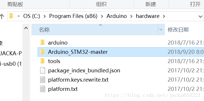
1、先去GitHub打包下载代码,解压放到Arduino\hardware目录; Arduino_STM32 https://github.com/rogerclarkmelbourne/Arduino_STM32
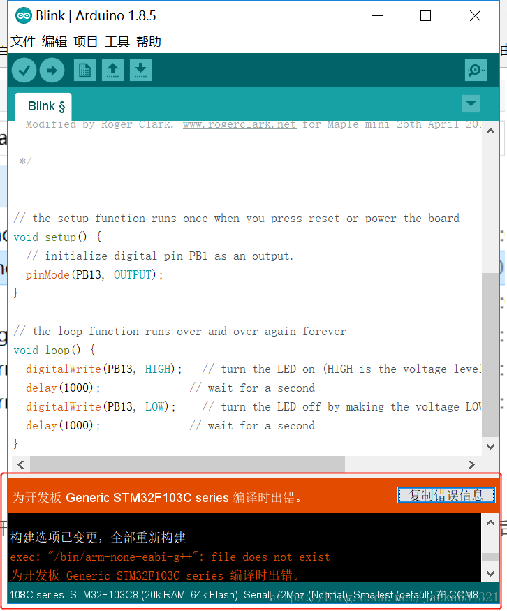
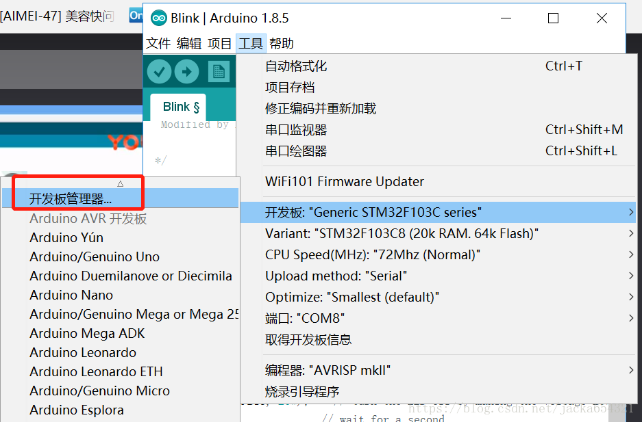
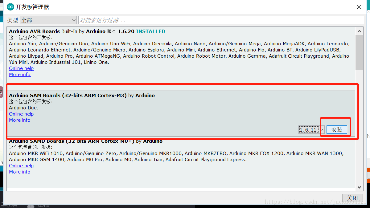
2、打开Arduino IDE然后按工具-开发板管理器,下载安装Arduino SAM开发板,不安装这个开发板后编译会出现arm-none-eabi-g++错误;
确保空间足够,务必安装完成,否则安装失败; 如果安装成功还是会报错,需要删除再安装,关闭IDE再打开测试;之前就是卡在这里折腾了好久。
3、测试硬件与连接: STM32F103C8T6小系统板 单片机 核心板 STM32开发板 学习板 ARM
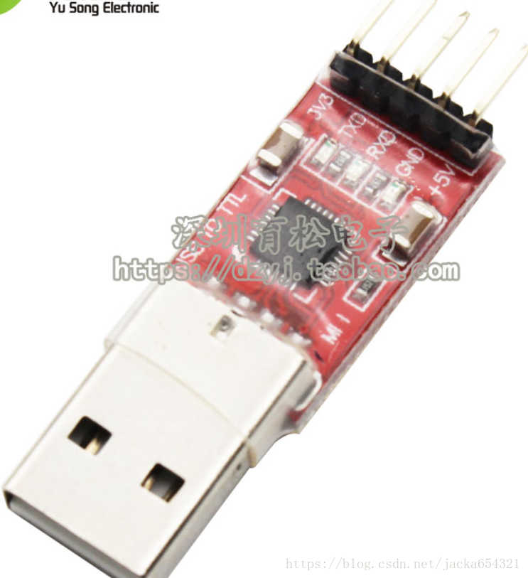
新款 CP2102模块 USB to TTL USB转串口模块UART 刷机升级板
4根杜邦线连接: 我们把USB TO TTL 模块的四根先 连接到我们的STM32的电源引脚以及串口引脚,这里用的是stm32f103c8t6 大家型号不一致也没事,按照这个步骤来,3.3v接到3.3v GND接到GND ,(要注意:模块与stm32的串口引脚 RX对应TX ,TX对应RX) 大家要通过串口给stm32烧录程序时要用串口1 ,也就是A9为TX引脚,A10为RX引脚。以下是接线图。 USB TO TTL STM32 3V3 V3 TXD A10 RXD A9 GND G +5V 不接
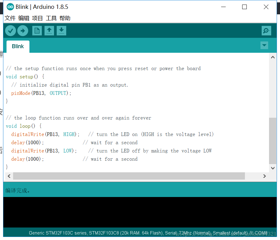
4、接好线后,打开arduino IDE,
5、连接好硬件后,打开例子,烧录测试:
修改测试代码,STM32 LED引脚为13; /* Blink Turns on an LED on for one second, then off for one second, repeatedly. Most Arduinos have an on-board LED you can control. On the Uno and Leonardo, it is attached to digital pin 13. If you're unsure what pin the on-board LED is connected to on your Arduino model, check the documentation at http://arduino.cc This example code is in the public domain. modified 8 May 2014 by Scott Fitzgerald Modified by Roger Clark. www.rogerclark.net for Maple mini 25th April 2015 , where the LED is on PB1 */ // the setup function runs once when you press reset or power the board void setup() { // initialize digital pin PB1 as an output. pinMode(PB13, OUTPUT); } // the loop function runs over and over again forever void loop() { digitalWrite(PB13, HIGH); // turn the LED on (HIGH is the voltage level) delay(1000); // wait for a second digitalWrite(PB13, LOW); // turn the LED off by making the voltage LOW delay(1000); // wait for a second }
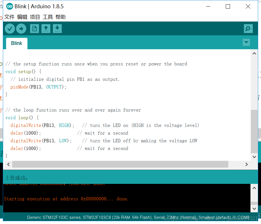
6、把跳线帽boot0置1; 默认 boot0 0(-), boot1 0(-), 改为 boot0 1(+), boot1 0(-); 设置后,按reset键,之后才开始烧录设置;
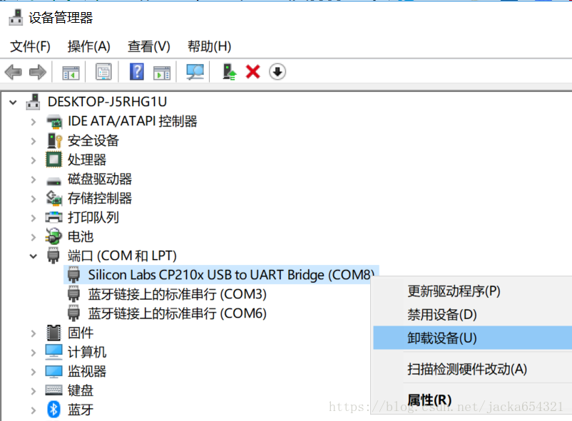
烧录完成后,恢复跳线帽,再按reset。 卸载串口设备: 断电状态下接线,在STM32引脚PB13接LED正极,在引脚G接GND(负极),用杜邦线连接起来; 上电,看到LED灯一闪一闪,代表已经成功运用。 |


【本文地址】
今日新闻 |
推荐新闻 |