C2000(F28027)烧录进flash |
您所在的位置:网站首页 › flash动作代码if语句 › C2000(F28027)烧录进flash |
C2000(F28027)烧录进flash
|
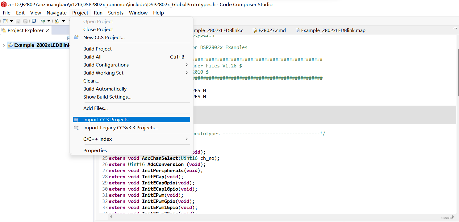
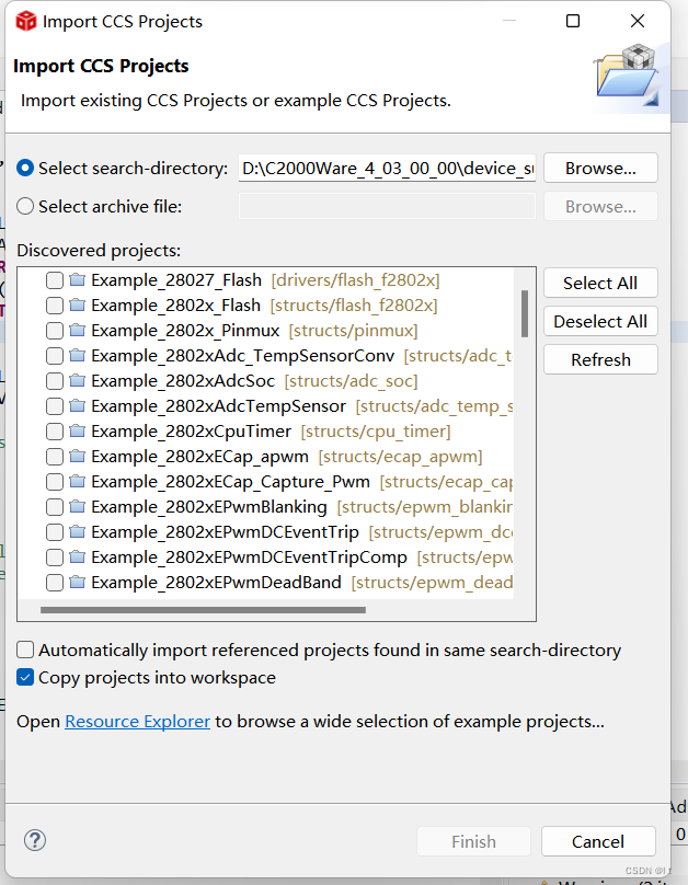
一、C2000环境下载 CCS(12.1.0)与C2000ware4.03 自己去找,网站都挺全的。(不建议去官网下,比较麻烦) 二、创建工程(建议直接拿例程改比较方便) 点击Project,选择import CCS project,点击Browse,
选择led_blink 将connection选择Texas instruments XDS 100v2 USB Debug Probe Linker command file 选择F28027.cmd,记得删掉原先的.cmd.文件 目前F28027.cmd有两种不一样的等会一一细说 (以前的cmd用的是方式二,c2000ware4.01用的是方式一) /* // TI File $Revision: /main/7 $ // Checkin $Date: July 6, 2009 17:25:36 $ //########################################################################### // // FILE: F28027.cmd // // TITLE: Linker Command File For F28027 Device // //########################################################################### // $TI Release: 2802x C/C++ Header Files V1.26 $ // $Release Date: February 2, 2010 $ //########################################################################### */ /* ====================================================== // For Code Composer Studio V2.2 and later // --------------------------------------- // In addition to this memory linker command file, // add the header linker command file directly to the project. // The header linker command file is required to link the // peripheral structures to the proper locations within // the memory map. // // The header linker files are found in \DSP2802_Headers\cmd // // For BIOS applications add: DSP2802x_Headers_BIOS.cmd // For nonBIOS applications add: DSP2802x_Headers_nonBIOS.cmd ========================================================= */ /* ====================================================== // For Code Composer Studio prior to V2.2 // -------------------------------------- // 1) Use one of the following -l statements to include the // header linker command file in the project. The header linker // file is required to link the peripheral structures to the proper // locations within the memory map */ /* Uncomment this line to include file only for non-BIOS applications */ /* -l DSP2802x_Headers_nonBIOS.cmd */ /* Uncomment this line to include file only for BIOS applications */ /* -l DSP2802x_Headers_BIOS.cmd */ /* 2) In your project add the path to \DSP2802x_headers\cmd to the library search path under project->build options, linker tab, library search path (-i). /*========================================================= */ /* Define the memory block start/length for the F28027 PAGE 0 will be used to organize program sections PAGE 1 will be used to organize data sections Notes: Memory blocks on F2802x are uniform (ie same physical memory) in both PAGE 0 and PAGE 1. That is the same memory region should not be defined for both PAGE 0 and PAGE 1. Doing so will result in corruption of program and/or data. The L0 memory block is mirrored - that is it can be accessed in high memory or low memory. For simplicity only one instance is used in this linker file. Contiguous SARAM memory blocks or flash sectors can be be combined if required to create a larger memory block. */ MEMORY { PAGE 0: /* Program Memory */ /* Memory (RAM/FLASH/OTP) blocks can be moved to PAGE1 for data allocation */ PRAML0 : origin = 0x008000, length = 0x000800 /* on-chip RAM block L0 */ OTP : origin = 0x3D7800, length = 0x000400 /* on-chip OTP */ FLASHD : origin = 0x3F0000, length = 0x002000 /* on-chip FLASH */ FLASHC : origin = 0x3F2000, length = 0x002000 /* on-chip FLASH */ FLASHA : origin = 0x3F6000, length = 0x001F80 /* on-chip FLASH */ CSM_RSVD : origin = 0x3F7F80, length = 0x000076 /* Part of FLASHA. Program with all 0x0000 when CSM is in use. */ BEGIN : origin = 0x3F7FF6, length = 0x000002 /* Part of FLASHA. Used for "boot to Flash" bootloader mode. */ CSM_PWL_P0 : origin = 0x3F7FF8, length = 0x000008 /* Part of FLASHA. CSM password locations in FLASHA */ IQTABLES : origin = 0x3FE000, length = 0x000B50 /* IQ Math Tables in Boot ROM */ IQTABLES2 : origin = 0x3FEB50, length = 0x00008C /* IQ Math Tables in Boot ROM */ IQTABLES3 : origin = 0x3FEBDC, length = 0x0000AA /* IQ Math Tables in Boot ROM */ ROM : origin = 0x3FF27C, length = 0x000D44 /* Boot ROM */ RESET : origin = 0x3FFFC0, length = 0x000002 /* part of boot ROM */ VECTORS : origin = 0x3FFFC2, length = 0x00003E /* part of boot ROM */ PAGE 1 : /* Data Memory */ /* Memory (RAM/FLASH/OTP) blocks can be moved to PAGE0 for program allocation */ /* Registers remain on PAGE1 */ BOOT_RSVD : origin = 0x000000, length = 0x000050 /* Part of M0, BOOT rom will use this for stack */ RAMM0 : origin = 0x000050, length = 0x0003B0 /* on-chip RAM block M0 */ RAMM1 : origin = 0x000400, length = 0x000400 /* on-chip RAM block M1 */ DRAML0 : origin = 0x008800, length = 0x000800 /* on-chip RAM block L0 */ FLASHB : origin = 0x3F4000, length = 0x002000 /* on-chip FLASH */ } /* Allocate sections to memory blocks. Note: codestart user defined section in DSP28_CodeStartBranch.asm used to redirect code execution when booting to flash ramfuncs user defined section to store functions that will be copied from Flash into RAM */ SECTIONS { /* Allocate program areas: */ .cinit : > FLASHA PAGE = 0 .pinit : > FLASHA, PAGE = 0 .text : > FLASHA PAGE = 0 codestart : > BEGIN PAGE = 0 ramfuncs : LOAD = FLASHA, RUN = PRAML0, LOAD_START(_RamfuncsLoadStart), LOAD_END(_RamfuncsLoadEnd), RUN_START(_RamfuncsRunStart), PAGE = 0 csmpasswds : > CSM_PWL_P0 PAGE = 0 csm_rsvd : > CSM_RSVD PAGE = 0 /* Allocate uninitalized data sections: */ .stack : > RAMM0 PAGE = 1 .ebss : > DRAML0 PAGE = 1 .esysmem : > DRAML0 PAGE = 1 /* Initalized sections go in Flash */ /* For SDFlash to program these, they must be allocated to page 0 */ .econst : > FLASHA PAGE = 0 .switch : > FLASHA PAGE = 0 /* Allocate IQ math areas: */ IQmath : > FLASHA PAGE = 0 /* Math Code */ IQmathTables : > IQTABLES, PAGE = 0, TYPE = NOLOAD /* Uncomment the section below if calling the IQNexp() or IQexp() functions from the IQMath.lib library in order to utilize the relevant IQ Math table in Boot ROM (This saves space and Boot ROM is 1 wait-state). If this section is not uncommented, IQmathTables2 will be loaded into other memory (SARAM, Flash, etc.) and will take up space, but 0 wait-state is possible. */ /* IQmathTables2 : > IQTABLES2, PAGE = 0, TYPE = NOLOAD { IQmath.lib (IQmathTablesRam) } */ /* Uncomment the section below if calling the IQNasin() or IQasin() functions from the IQMath.lib library in order to utilize the relevant IQ Math table in Boot ROM (This saves space and Boot ROM is 1 wait-state). If this section is not uncommented, IQmathTables2 will be loaded into other memory (SARAM, Flash, etc.) and will take up space, but 0 wait-state is possible. */ /* IQmathTables3 : > IQTABLES3, PAGE = 0, TYPE = NOLOAD { IQmath.lib (IQmathTablesRam) } */ /* .reset is a standard section used by the compiler. It contains the */ /* the address of the start of _c_int00 for C Code. /* /* When using the boot ROM this section and the CPU vector */ /* table is not needed. Thus the default type is set here to */ /* DSECT */ .reset : > RESET, PAGE = 0, TYPE = DSECT vectors : > VECTORS PAGE = 0, TYPE = DSECT } /* //=========================================================================== // End of file. //=========================================================================== */如果cmd是这样的,那么将以下代码加入主函数前 extern Uint16 RamfuncsLoadStart; extern Uint16 RamfuncsLoadEND; extern Uint16 RamfuncsRunStart; void MemCopy(Uint16 *SourceAddr, Uint16* SourceEndAddr, Uint16* DestAddr) { while(SourceAddr < SourceEndAddr) { *DestAddr++ = *SourceAddr++; } return; }然后将如下代码放在主函数最前面: MemCopy(&RamfuncsLoadStart, &RamfuncsLoadEnd, &RamfuncsRunStart); InitFlash();可以使用以下流水灯代码 #include "DSP28x_Project.h" // Device Headerfile and Examples Include File extern Uint16 RamfuncsLoadStart; extern Uint16 RamfuncsLoadEND; extern Uint16 RamfuncsRunStart; void MemCopy(Uint16 *SourceAddr, Uint16* SourceEndAddr, Uint16* DestAddr) { while(SourceAddr < SourceEndAddr) { *DestAddr++ = *SourceAddr++; } return; } void Gpio_select(void); void main(void) { MemCopy(&RamfuncsLoadStart, &RamfuncsLoadEnd, &RamfuncsRunStart); InitFlash(); // Step 1. Initialize System Control: // PLL, WatchDog, enable Peripheral Clocks // This example function is found in the DSP2802x_SysCtrl.c file. InitSysCtrl(); // Step 2. Initalize GPIO: // This example function is found in the DSP2802x_Gpio.c file and // illustrates how to set the GPIO to it's default state. // InitGpio(); // Skipped for this example // For this example use the following configuration: Gpio_select(); // Step 3. Clear all interrupts and initialize PIE vector table: // Disable CPU interrupts DINT; // Initialize PIE control registers to their default state. // The default state is all PIE interrupts disabled and flags // are cleared. // This function is found in the DSP2802x_PieCtrl.c file. InitPieCtrl(); // Disable CPU interrupts and clear all CPU interrupt flags: IER = 0x0000; IFR = 0x0000; // Initialize the PIE vector table with pointers to the shell Interrupt // Service Routines (ISR). // This will populate the entire table, even if the interrupt // is not used in this example. This is useful for debug purposes. // The shell ISR routines are found in DSP2802x_DefaultIsr.c. // This function is found in DSP2802x_PieVect.c. InitPieVectTable(); // Step 4. Initialize all the Device Peripherals: // This function is found in DSP2802x_InitPeripherals.c // InitPeripherals(); // Not required for this example // Step 5. User specific code: while(1) { GpioDataRegs.GPADAT.all = 0x0000000e; DELAY_US(1000000); GpioDataRegs.GPADAT.all = 0x0000000d; DELAY_US(1000000); GpioDataRegs.GPADAT.all = 0x0000000b; DELAY_US(1000000); GpioDataRegs.GPADAT.all = 0x00000007; DELAY_US(1000000); GpioCtrlRegs.GPAMUX1.all = 0x00000000; // All GPIO } } void Gpio_select(void) { EALLOW; GpioCtrlRegs.GPAMUX1.all = 0x00000000; // All GPIO GpioCtrlRegs.GPAMUX2.all = 0x00000000; // All GPIO GpioCtrlRegs.GPBMUX1.all = 0x00000000; // All GPIO GpioCtrlRegs.GPADIR.all = 0xFFFFFFFF; // All outputs GpioCtrlRegs.GPBDIR.all = 0x0000000F; // All outputs EDIS; }
然后点锤子和向下的箭头。S1为on-on-on。 有程序后断电,将S1变为on-on-off。 此时程序仍能运行。 另一种cmd文件只有以下段代码不同 .TI.ramfunc : {} LOAD = FLASHA, RUN = PRAML0, LOAD_START(_RamfuncsLoadStart), LOAD_END(_RamfuncsLoadEnd), RUN_START(_RamfuncsRunStart), PAGE = 0 #else ramfuncs : LOAD = FLASHA, RUN = PRAML0, LOAD_START(_RamfuncsLoadStart), LOAD_END(_RamfuncsLoadEnd), RUN_START(_RamfuncsRunStart), PAGE = 0则需要另一种代码: 在 main.c 文件中添加全局变量 extern Uint16 RamfuncsLoadStart; extern Uint16 RamfuncsLoadEnd; extern Uint16 RamfuncsRunStart; extern Uint16 RamfuncsLoadSize;在 main.c 文件中的 main()函数开头部分添加语句 InitSysCtr1(); memcpy ( &RamfuncsRunStart, &RamfuncsLoadStart, (Uint32 )&RamfuncsLoadSize); InitFlash();然后一样进行运行。 |

【本文地址】
今日新闻 |
推荐新闻 |