OsgEarth3基础3D图形实现 |
您所在的位置:网站首页 › 3d图形填充颜色 › OsgEarth3基础3D图形实现 |
OsgEarth3基础3D图形实现
|
OsgEarth3基础3D图形实现
主要难点Geometry能力姿态支持
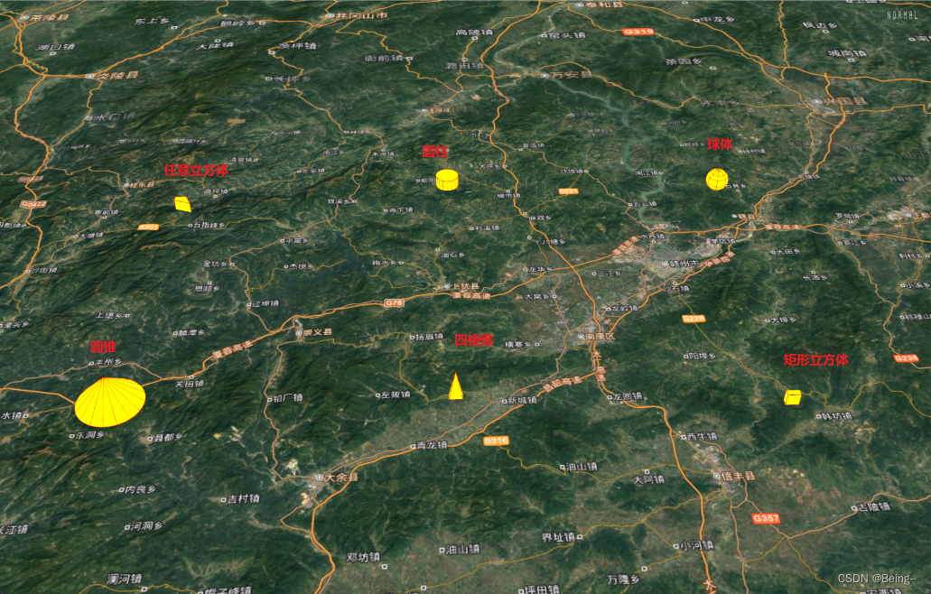
任意立方体 PolygonCube矩形立方体 Box圆锥体 Cone圆柱体 Cylinder四棱锥 Pyramid球体 Sphere源码示例ElementGeometry圆锥Cone
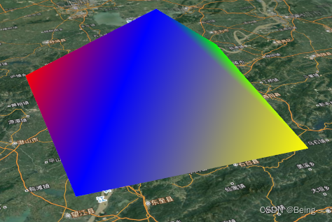
这里尝试在通过OsgEarth提供的各种图形绘制方法,实现基础的3D图形。每个图形除了基础的设置外,尝试提供:位置(Position)、姿态(Posture)、**填充色(FillColor)、描边色(ProfileColor/LineColor)的设置,在具体的框架性代码环境中也可以尝试抽象出基类,这里主要关注具体实现。 其中osg::Geometry提供的顶点绘制能力,可以满足对各种形状的实现,所以这里也是为了绘制需要图形的描边线,进行了简单封装,通过提供顶点数组、顶点坐标、图形样式、线颜色、线宽完成绘制。 事实上它可以包含: Statetset信息:比如设置透明度支持: m_pGeom->getOrCreateStateSet()->setMode(GL_BLEND, osg::StateAttribute::ON); m_pGeom->getOrCreateStateSet()->setRenderingHint(osg::StateSet::TRANSPARENT_BIN); Primitive列表和顶点数组:确定顶点索引,添加多个几何体 提供的几何体类型也很丰富,具体描述可以详见该博客https://blog.csdn.net/qq_36881934/article/details/107912706 enum Mode { POINTS = GL_POINTS, LINES = GL_LINES, LINE_STRIP = GL_LINE_STRIP, LINE_LOOP = GL_LINE_LOOP, TRIANGLES = GL_TRIANGLES, TRIANGLE_STRIP = GL_TRIANGLE_STRIP, TRIANGLE_FAN = GL_TRIANGLE_FAN, QUADS = GL_QUADS, QUAD_STRIP = GL_QUAD_STRIP, POLYGON = GL_POLYGON, LINES_ADJACENCY = GL_LINES_ADJACENCY, LINE_STRIP_ADJACENCY = GL_LINE_STRIP_ADJACENCY, TRIANGLES_ADJACENCY = GL_TRIANGLES_ADJACENCY, TRIANGLE_STRIP_ADJACENCY = GL_TRIANGLE_STRIP_ADJACENCY, PATCHES = GL_PATCHES };有特殊顺序的可以通过顶点索引,设置顶点坐标的方式添加: osg::ref_ptr geometry = new osg::Geometry;//创建一个几何体对象 osg::ref_ptr v = new osg::Vec3Array; v->push_back(osg::Vec3(0.0f, 0.0f, 0.0f)); v->push_back(osg::Vec3(2.0f, 0.0f, 0.0f)); v->push_back(osg::Vec3(1.0f, -1.0f, 1.0f)); v->push_back(osg::Vec3(2.0f, -2.0f, 0.0f)); v->push_back(osg::Vec3(0.0f, -2.0f, 0.0f)); geometry->setVertexArray(v);//设置几何体顶点数据 osg::ref_ptr quad = new osg::DrawElementsUInt(osg::PrimitiveSet::TRIANGLE_STRIP, 0);//指定绘图基元为绘制多段三角形 quad->push_back(0); quad->push_back(1); quad->push_back(2); quad->push_back(3); quad->push_back(4); quad->push_back(0); quad->push_back(2); geometry->addPrimitiveSet(quad);//添加到几何体简单的顶点连接顺序,可以直接通过geometry->addPrimitiveSet(new osg::DrawArrays(osg::PrimitiveSet::LINE_LOOP, 0, vcArray->size()));添加。 颜色/纹理数组列表 颜色可以是渐变色,也可以是纯色,主要在于设置的颜色数组,以及颜色绑定模式。 如渐变色可以根据顶点: osg::ref_ptr vc = new osg::Vec4Array;//创建颜色数组 vc->push_back(osg::Vec4(1.0f, 0.0f, 0.0f, 1.0f)); vc->push_back(osg::Vec4(0.0f, 1.0f, 0.0f, 1.0f)); vc->push_back(osg::Vec4(0.0f, 0.0f, 1.0f, 1.0f)); vc->push_back(osg::Vec4(1.0f, 1.0f, 0.0f, 1.0f)); vc->push_back(osg::Vec4(0.0f, 0.0f, 1.0f, 1.0f)); geometry->setColorArray(vc); geometry->setColorBinding(osg::Geometry::BIND_PER_VERTEX);//设置颜色绑定模式
对于3D图形的属性,姿态肯定也是重点:俯仰、横滚、航向。 这里通过osg::MatrixTransform的rotate方式实现。 首先将Matrix加入到osgEarth::GeoTransform节点,Drawable加入到Matrix节点作为Child,就可以控制Drawable图形的姿态了。 // GeoTransform m_pGeoTransform = new osgEarth::GeoTransform(); m_pMatrix = new osg::MatrixTransform; m_pGeoTransform->addChild(m_pMatrix); m_pMatrix->addChild(m_pDrawable); m_pMatrix->setMatrix( osg::Matrix::rotate( osg::DegreesToRadians(vPos.x()), osg::X_AXIS, osg::DegreesToRadians(vPos.y()), osg::Y_AXIS, osg::DegreesToRadians(vPos.z()), osg::Z_AXIS)); }
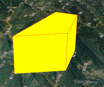
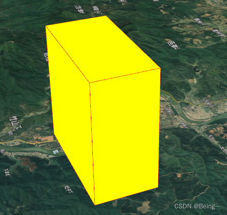
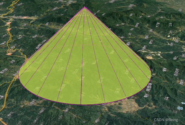
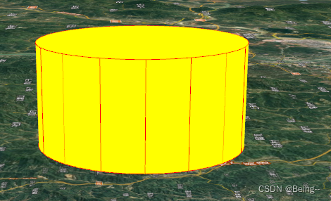
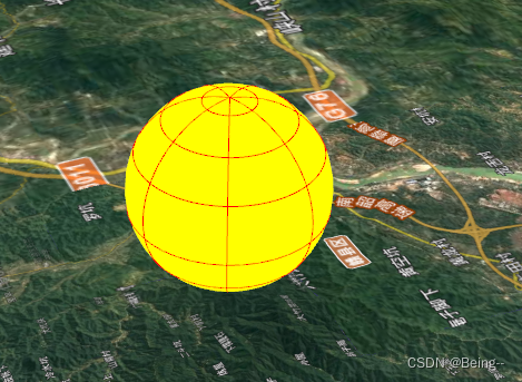
使用osgEarth::FeatureNode实现,它对矢量的点线面绘制提供了很好的解决方案,包括与地形的贴合方式(osgEarth::AltitudeSymbol::Clamping),与矢量图层的结合方式等。这里主要通过设置一组坐标信息,绘制立方体。 虽然osgEarth::FeatureNode通过设置顶点坐标,也可以画出矩形立方体,但是在实践的过程中发现,高度实现,更准确讲是实现的面向上“挤出”后的效果,而且地面没有封顶,也没有描边线。 m_Style.getOrCreate()->height() = dHeightMeter;为了实现一个“像样的”矩形立方体,使用了osg::Box结合osg::ShapeDrawable实现,但是osg的绘制体没有描边色,所以也是通过osg::Geometry实现了Box的边线。 使用了osg::Cone结合osg::ShapeDrawable实现,也是通过osg::Geometry实现了底部圆形描边+分段线描边。 注意中心点在高度的1/3处,所以如果要控制中心点在底部,可以通过让osgEarth::GeoTransform->addChild(),加入一个Relative的osg::MatrixTransform去偏移到底部。 使用了osg::Cylinder结合osg::ShapeDrawable实现,也是通过osg::Geometry实现了上下圆形描边+分段线描边。 另一个重点是,Cylinder的实现最开始我是尝试的osgEarth::CircleNode,也可以达到圆柱的效果,但是没办法自己控制分段线的条数,也不能直接根据Matrix修改姿态,高度也是“挤出”形式,也是为了统一内部实现,改为了现在的osg::Cylinder,虽然分段线多一点点实现过程,但效果会更好。 注意中心点在高度的1/2处,所以如果要控制中心点在底部,可以通过让osgEarth::GeoTransform->addChild(),加入一个Relative的osg::MatrixTransform去偏移到底部。 这个图形,可以说是“纯手工”绘制,因为图形和描边线,都是用的osg::Geometry实现,osg::Geometry通过addPrimitiveSet两个顶点数组索引,完成实现。 最开始没有理解到osg::Geometry的精髓,使用了两个osg::Geometry分别实现三角面和连线,事实上addPrimitiveSet已经给出了解决方案,已经把图形组的接口给抽象好了。 重要代码: { osg::ref_ptr quad = new osg::DrawElementsUInt(osg::PrimitiveSet::TRIANGLE_STRIP, 0);//指定绘图基元为绘制多段三角形 quad->push_back(0); quad->push_back(1); quad->push_back(2); quad->push_back(3); quad->push_back(0); quad->push_back(4); quad->push_back(1); quad->push_back(4); quad->push_back(2); quad->push_back(3); m_pGeometry->addPrimitiveSet(quad);//添加到几何体 } { osg::ref_ptr quad = new osg::DrawElementsUInt(osg::PrimitiveSet::LINE_LOOP, 0);//指定绘图基元为绘制闭合线 quad->push_back(0); quad->push_back(1); quad->push_back(2); quad->push_back(3); quad->push_back(4); quad->push_back(0); quad->push_back(4); quad->push_back(1); quad->push_back(2); quad->push_back(4); quad->push_back(3); m_pGeometry->addPrimitiveSet(quad);//添加到几何体 } // Color m_cSurface = Color::White; m_cLine = Color(0, 0, 0, 0); m_vcColor = new osg::Vec4Array; m_vcColor->push_back(m_cSurface); m_vcColor->push_back(m_cLine); m_pGeometry->setColorArray(m_vcColor, osg::Array::BIND_PER_PRIMITIVE_SET); m_pGeometry->getOrCreateStateSet()->setMode(GL_BLEND, osg::StateAttribute::ON); m_pGeometry->getOrCreateStateSet()->setRenderingHint(osg::StateSet::TRANSPARENT_BIN); void CPyramidObject3D::Rebuild() { if (NULL == m_vcGeom) { return; } m_vcGeom->clear(); m_vcGeom->push_back(osg::Vec3d(-m_dX/2, -m_dY/2, 0.0)); m_vcGeom->push_back(osg::Vec3d(-m_dX/2, m_dY/2, 0.0)); m_vcGeom->push_back(osg::Vec3d(m_dX/2, m_dY/2, 0.0f)); m_vcGeom->push_back(osg::Vec3d(m_dX/2, -m_dY/2, 0.0)); m_vcGeom->push_back(osg::Vec3d(0.0, 0.0, m_dH)); m_pGeometry->setVertexArray(m_vcGeom); } 球体 Sphere使用了osg::Sphere结合osg::ShapeDrawable实现,也是通过osg::Geometry实现了横竖的分段线绘制。主要是对于球体,需要有分段线才能体现立体感,否则和2D圆形的区别在某些角度就不明显了。 3D图形的实现源码之前分享过一次,这次为了描边线和姿态又尝试修改了一些实现,具体的环境搭建,可以看上一篇文章。 有一些实现不足的多多指教,对于OsgEarth的学习也在摸索中。 封装基于Osg+OsgEarth3实现的3D基础图元类,每个类提供各个图元的基础参数设置。封装的图元类:PolygonCubeObject3D(任意立方体)、CylinderObject3DEx(圆柱)、SphereObject3D(球体)、ConeObject3D(圆锥)、PyramidObject3D(四棱锥)、BoxObject3D(矩形立方体)。OsgEarthMapViewer内包含响应按钮事件(hand函数),以动态修改图元属性的测试。注意测试指定图元属性修改时,需要打开指定handle的注释,并对应switch内的按键进行操作。建议自行建立工程后,编译源码后进行测试(内含main.cpp),随时修改以及时看到变化情况,了解各个参数对绘制的影响。 (相比上面的2D图元绘制的代码,3D图元绘制的资源内,封装了对绘制属性的设置修改,即封装成类,提供到接口操作)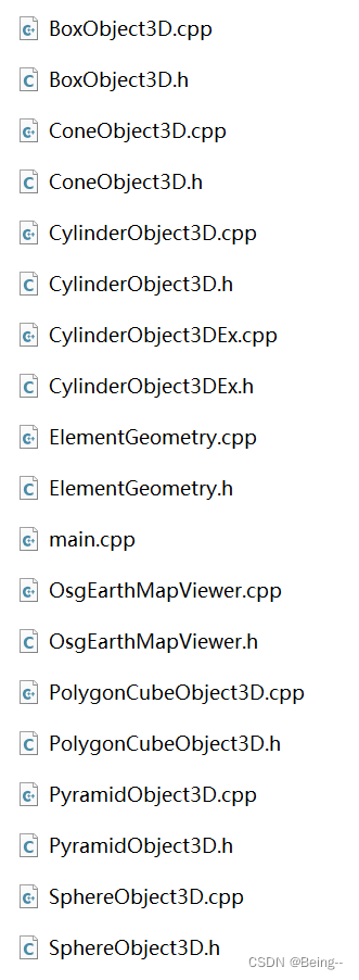
这里提供ElementGeometry和Cone的示例实现,其它的就是依葫芦画瓢了。 ElementGeometry为了其它图元内部更好地实现描边线而进行的封装 #ifndef ElementGeometry_h__ #define ElementGeometry_h__ #include #include #include #include #include #include class CElementGeometry { public: CElementGeometry(); ~CElementGeometry(); osg::ref_ptr GetGeometry() const; void SetVertexArray(osg::Vec3Array* array); void AddPrimitiveSet(osg::PrimitiveSet* quad); void RemovePrimitiveSet(int nIndex); void SetColor(const osgEarth::Color& c); void SetColorArray(osg::Array* array, osg::Array::Binding binding); void SetWidth(float fWidth); private: osg::ref_ptr m_pGeom; osg::ref_ptr m_pLineWidth; }; #endif // ElementGeometry_h__ #include "ElementGeometry.h" CElementGeometry::CElementGeometry() { m_pGeom = new osg::Geometry; m_pGeom->getOrCreateStateSet()->setMode(GL_BLEND, osg::StateAttribute::ON); m_pGeom->getOrCreateStateSet()->setRenderingHint(osg::StateSet::TRANSPARENT_BIN); } CElementGeometry::~CElementGeometry() { m_pGeom = NULL; } osg::ref_ptr CElementGeometry::GetGeometry() const { return m_pGeom; } void CElementGeometry::SetVertexArray(osg::Vec3Array* array) { m_pGeom->setVertexArray(array); } void CElementGeometry::AddPrimitiveSet(osg::PrimitiveSet* quad) { m_pGeom->addPrimitiveSet(quad); } void CElementGeometry::RemovePrimitiveSet(int nIndex) { m_pGeom->removePrimitiveSet(nIndex); } void CElementGeometry::SetColor(const osgEarth::Color& c) { osg::Vec4Array* vecColorSurface = new osg::Vec4Array; vecColorSurface->push_back(c); m_pGeom->setColorArray(vecColorSurface, osg::Array::BIND_OVERALL); } void CElementGeometry::SetColorArray(osg::Array* array, osg::Array::Binding binding) { m_pGeom->setColorArray(array, binding); } void CElementGeometry::SetWidth(float fWidth) { if (fWidth > 0.0) { if (!m_pLineWidth.valid()) { m_pLineWidth = new osg::LineWidth(1.0f); m_pGeom->getOrCreateStateSet()->setAttribute(m_pLineWidth, osg::StateAttribute::OFF); } m_pLineWidth->setWidth(fWidth); m_pGeom->setNodeMask(0xff); } else { m_pGeom->setNodeMask(0); } m_pGeom->dirtyDisplayList(); } 圆锥Cone #ifndef ConeObject3D_h__ #define ConeObject3D_h__ #include #include #include #include #include #include class CElementGeometry; class CConeObject3D { public: CConeObject3D(const osgEarth::SpatialReference* mapSRS); ~CConeObject3D(); osg::ref_ptr GetObjectNode() const; void SetCenter(const osg::Vec3d& vPt); void SetRadius(double dRadiusMeter); void SetHeight(double dHeightMeter); void SetPosture(const osg::Vec3d& vPos); void SetFillColor(const osgEarth::Color& c); void SetProfileColor(const osgEarth::Color& c); void SetProfileWidth(float dWidth); void SetSegmentation(int nNum); private: void BuildProfile(double dRadius, double dHeight, int nNum); private: const osgEarth::SpatialReference* m_pSRS; osg::ref_ptr m_pGeoTransform; osg::ref_ptr m_pMatrix; osg::ref_ptr m_pRelativeMatrix; osg::Vec3d m_vPosture; osg::ShapeDrawable* m_pDrawable; osg::Cone* m_pCone; double m_dRadius; double m_dHeight; osgEarth::Color m_lineColor; float m_fLineWidth; std::vector m_vecGeometry; }; #endif // ConeObject3D_h__ #include "ConeObject3D.h" #include "osg/Math" #include "ElementGeometry.h" using namespace osgEarth; CConeObject3D::CConeObject3D(const osgEarth::SpatialReference* mapSRS) : m_pSRS(mapSRS) , m_dRadius(0.0) , m_dHeight(0.0) , m_fLineWidth(0.0) { m_pCone = new osg::Cone(); m_pDrawable = new osg::ShapeDrawable(m_pCone); m_pDrawable->getOrCreateStateSet()->setMode(GL_BLEND, osg::StateAttribute::ON); m_pDrawable->getOrCreateStateSet()->setRenderingHint(osg::StateSet::TRANSPARENT_BIN); m_pGeoTransform = new osgEarth::GeoTransform(); m_pMatrix = new osg::MatrixTransform; m_pRelativeMatrix = new osg::MatrixTransform; m_pGeoTransform->addChild(m_pMatrix); m_pMatrix->addChild(m_pDrawable); m_pMatrix->addChild(m_pRelativeMatrix); SetRadius(5000); SetHeight(1000); } CConeObject3D::~CConeObject3D() { SetSegmentation(-1); m_pGeoTransform = NULL; } osg::ref_ptr CConeObject3D::GetObjectNode() const { return m_pGeoTransform; } void CConeObject3D::SetCenter(const osg::Vec3d& vPt) { m_pGeoTransform->setPosition(osgEarth::GeoPoint(m_pSRS, vPt, osgEarth::ALTMODE_RELATIVE)); } void CConeObject3D::SetRadius(double dRadiusMeter) { m_pCone->setRadius(dRadiusMeter); m_pDrawable->dirtyDisplayList(); m_pGeoTransform->dirtyBound(); m_dRadius = dRadiusMeter; SetSegmentation(m_vecGeometry.size() - 1); } void CConeObject3D::SetHeight(double dHeightMeter) { m_dHeight = dHeightMeter; m_pCone->setHeight(dHeightMeter); // 原始中心点在图形中间 h的1/4处 m_pRelativeMatrix->setMatrix( osg::Matrix::rotate(0.0, osg::X_AXIS, 0.0, osg::Y_AXIS, 0.0, osg::Z_AXIS) *osg::Matrix::translate(osg::Vec3d(0, 0, -dHeightMeter / 4))); SetPosture(m_vPosture); m_pDrawable->dirtyDisplayList(); m_pGeoTransform->dirtyBound(); SetSegmentation(m_vecGeometry.size() - 1); } void CConeObject3D::SetPosture(const osg::Vec3d& vPos) { m_vPosture = vPos; m_pMatrix->setMatrix( osg::Matrix::rotate( osg::DegreesToRadians(vPos.x()), osg::X_AXIS, osg::DegreesToRadians(vPos.y()), osg::Y_AXIS, osg::DegreesToRadians(vPos.z()), osg::Z_AXIS) *osg::Matrix::translate(osg::Vec3d(0, 0, m_dHeight / 4))); } void CConeObject3D::SetFillColor(const osgEarth::Color& c) { m_pDrawable->setColor(c); } void CConeObject3D::SetProfileColor(const osgEarth::Color& c) { for (int i = 0; i for (int i = 0; i for (int i = 0; i if (nNum osg::ref_ptr vcArray = new osg::Vec3Array; int n = pow(2.0, 7); double dAngle = 360.0 / n; for (int i = 0; i double dAngle = 360.0 / nNum; for (int i = 0; i |

【本文地址】
今日新闻 |
推荐新闻 |